Extinguishing control panel. User manual
22 June 2011 9
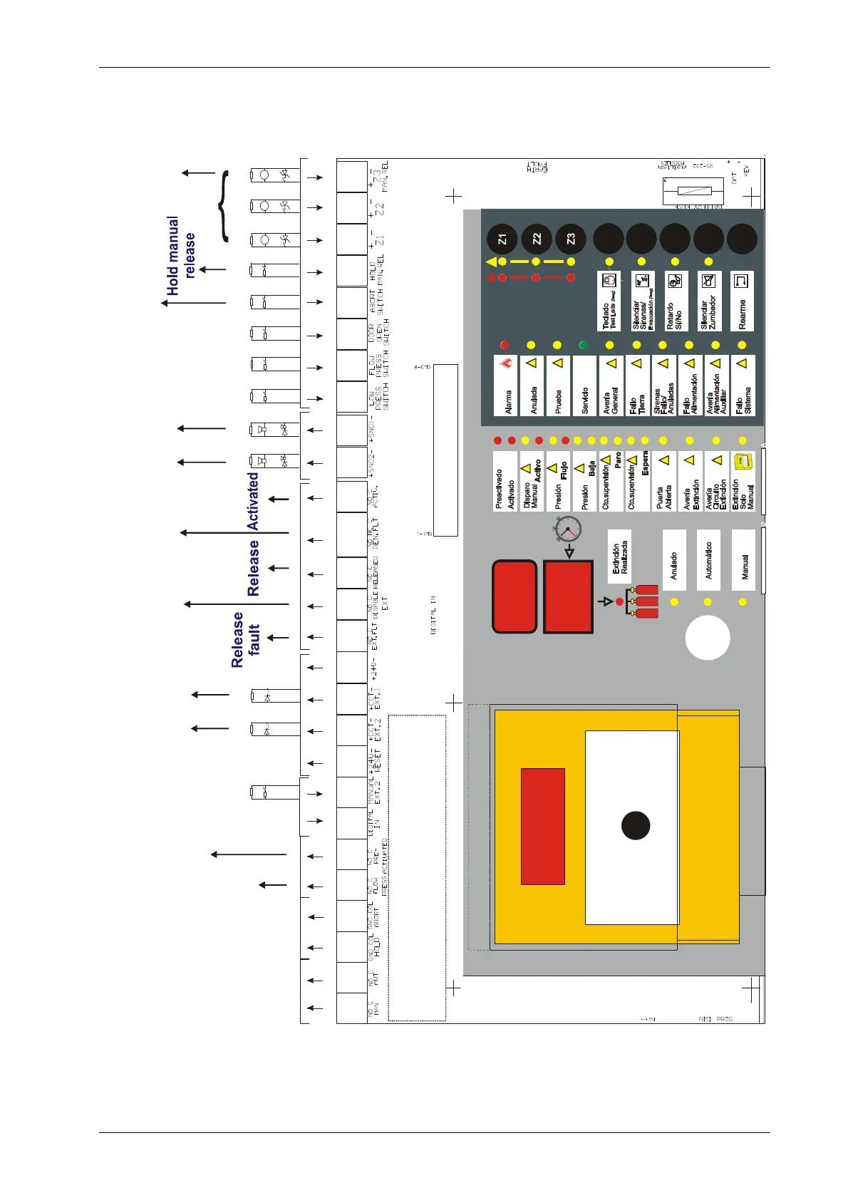
2. CONNECTIONS AND WIRING
2.1 Release control panel board diagram
Extinguishing
release
2 1
Sounder
2 1
GAS
1 2 3 4 5 6 A B 9 10 11 12 13 14 15 16 17 18 19 C D E F G H I J
1
2
3
4
5
6
7
8
RFL
6K8
RFL
6K8
RFL
6K8
RFL
6K8
RFL
6K8
RFL
6K8
RFL
6K8
RFL
6K8
RFL
6K8
RFL
6K8
RFL
6K8
RFL
6K8
RFL
6K8
ZONES
Manual
release
Abort
switch
Fault
Disabled
release
Preactive or
Alarm
Flow
R R C C R R I E A S S A R R R R R S S E E E E E E E E
CAPTION:
R: Relay output
C: Open collector output
I: Digital input NO/NC
S: Monitored output
A: 24V Power
E: Monitored input
Note: Relays 1, 2, 5, 6, 13, 14, 15 and 17 are NO (Normally Open) but can become NC (normally closed). Contact
with Honeywell Life Safety Iberia Technical Department.
Relay 16 (fault) is NO/NC (Normally Open / Normally Closed)

 Loading...


