Extinguishing control panel. User manual
22 June 2011 3
1.5. General.
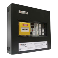
This release control panel has been designed to manage correctly and according to
EN12094:1/2003 and EN54-2 and EN54-4/A2:2006 the automatic release sequence of any
extinguishing system. This compact control panel has 2 microprocessors to increase safety and
includes a switched 65W power supply with battery charger.
The control panel has 3 input zones for direct connection of 2-wire conventional detectors or
external release call points. The control panel also includes two release monitored circuits and
two sounder outputs with different frequencies in order to identify each release state (Pre-
Activated Activated, Hold/Abort Condition and Imminent Release). At the front panel there are
function pushbuttons, a release call point, a 2-digit countdown timer that indicates the seconds
left for release activation (after release acknowledgement and with GAS sign on), and a
keyswitch for operating mode selection: Automatic, Manual and Disabled.
There are a number of input circuits: Hold device, release abort device, low and flow pressure
monitoring and open door monitoring, being able to cancel the extinguishing release. Apart from
two release outputs there are also status outputs (Pre-activated, activated or extinguishing
release in process), general fault, automatic release inhibited output and fault output in release
circuit. The Release control panel also includes relay outputs in order to indicate the release
status (automatic, manual or system disabled), whether the control panel is in hold or abort mode
and the flow detector status and two more outputs for Resettable and non-resettable power
supply.
The Release control panel allows the connection to a remote station and telephone
communicator through Ademco Contact ID format. History log is included.
This control panel can be easily configured by means of built-in microswitches. Extinguishing
delays can be programmed in five second steps from 0 to 60 seconds and 4 different soak delays
can also be configured (at 2 seconds, 60 seconds, from 0 to 300 seconds or from 0 to RESET).
This extinguishing control panel has been designed in compliance with EN12094:1 2003: Fixed
fire fighting systems – Components for gas extinguishing systems - Part 1: Requirements
and test methods for electrical automatic control and delay devices.
Moreover, Release control panel meets the following EN12094:1 Options with requirements:
4.17 Delay of extinguishing signal.
4.18 Signal representing the flow of extinguishing agent.
4.19 Monitoring of the status of components. (Low/flow pressure)
4.20 Emergency hold device. (Sequence b)
4.21 Control of flooding time.
4.23 Manual only mode.
4.26 Triggering of equipment outside the system. (Required in Belgium).
4.27 Emergency abort device.
4.30 Activation of alarm devices with different signals.
NOTE: While every effort is made to ensure the accuracy of the content of this manual, the
manufacturer reserves the right to change the information without notice.

 Loading...


