Extinguishing control panel. User manual
22 June 2011 11
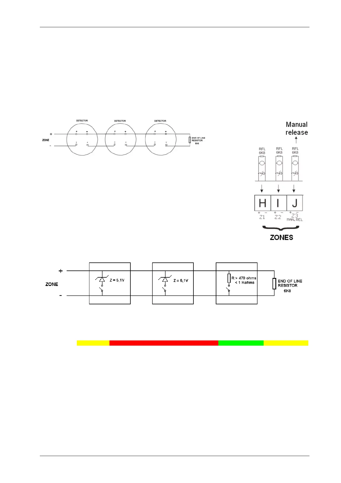
2.2 Detection zone wiring. Terminal blocks: H (Z1), I (Z2) y J (Z3)
The detection zones provide a nominal 24Vdc to power conventional detectors and call points.
Detection zone circuits must be wired as a single circuit with no spurs or T junctions to enable the
monitoring circuit to work correctly.
When using Notifier series 800 or Morley ECO1000 detectors, up to 32 detectors can be installed.
2.2.b. ZONE 1 AND 2 WIRING WITH MCP OR ZONE 3 AS GAS
RELEASE CALL POINT (SW1-5 OFF)
When it is necessary to distinguish between the indication of a detector
alarm and a call point alarm in the zone, a 5V1 Zener must be installed in
Zones 1 and 2.
The detector alarm will be indicated by the led in flashing mode and the call
point alarm will be indicated by the led in steady mode.
If Zone 3 is set as Manual Release zone (SW1-5 in OFF position) it is not
necessary to install a 5.1Vdc Zener to indicate the call point alarms.
Zone status according to power ratings:
% 0 15 27 74 94 100
Description Short circuit Call point alarm Detector alarm Normal Status 6K8 Open circuit
Volts 4 7 18 23 25
Resistor 0 --------------- 50 100 ------------------------ 150 200 -------------------------- 1K2 1K5 ------ 6K8 ------ 10K
(Approximate values)

 Loading...


