RP-2001 Series Manual — P/N 52985:D5 1/26/2017 43
ANN-BUS Devices Installation
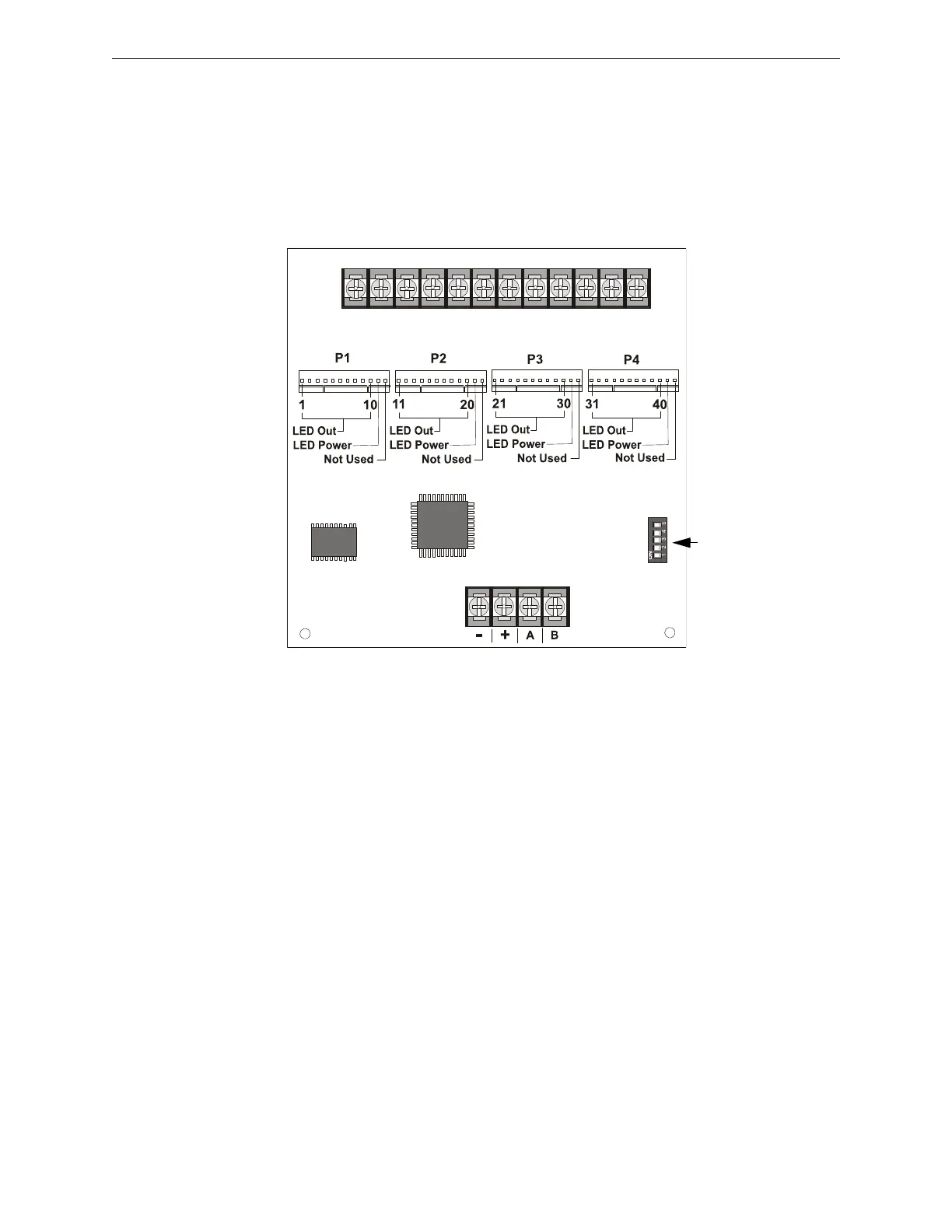
N-ANN-I/O Board Layout
Figure 2.20 illustrates the N-ANN-I/O board showing locations of screw terminals for connection
to the FACP, pin connectors for connecting LEDs and the DIP switch for selecting the ANN-BUS
ID number.
Specifications
• Max. ANN-BUS Voltage: 28 VDC
• Max. Current:
Alarm: 200 mA
Standby: 35 mA
Each LED: 10 mA
• Operating Temperature: 32
o
F to 120
o
F (0
o
C to 49
o
C)
• For indoor use in a dry location only
Figure 2.20 N-ANN-I/O Board Layout
ANN-BUS (ID#)
Address DIP
switch
ANN-BUS Connector
Terminals not used (future)

 Loading...


