88 RP-2002 Series Manual — P/N 53039:E6 1/26/2017
Operating Instructions Read Status
4.15.1 FACP Configuration
Pressing 1 while viewing Read Status Screen #1 will display the type of configuration programmed
into the FACP (refer to “FACP CONFIG (Application Templates)” on page 53). As an example, if
Template 1 was programmed as the FACP configuration, the following screen will be displayed:
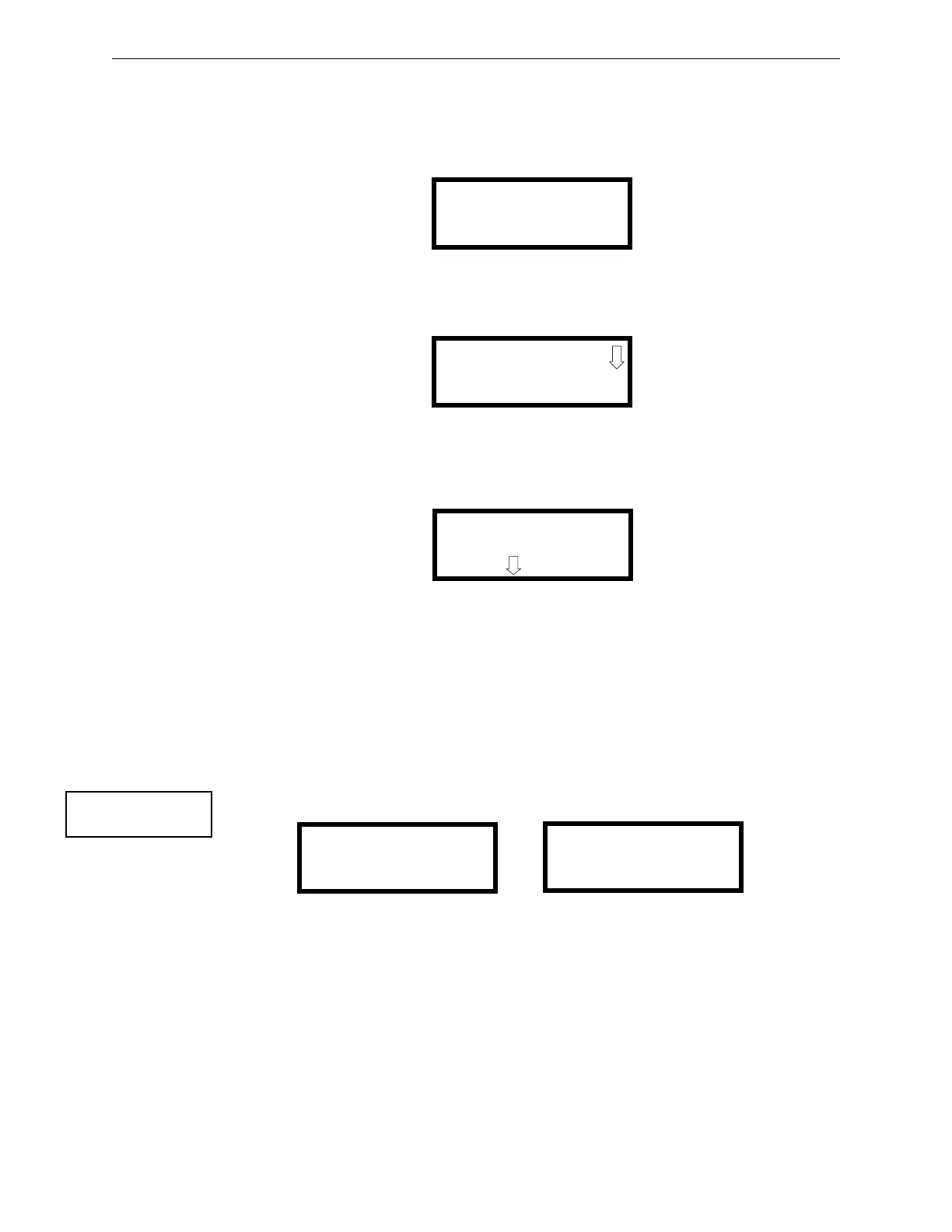
4.15.2 Input Zones
Pressing 2 while viewing Read Status Screen #1 will cause the following screens to be displayed:
Pressing the down arrow key will allow the selection of Zones 4-6.
The operator selects the zone which is to be viewed by pressing the number corresponding to the
desired zone in each screen. For example, if 1 is pressed in the first screen, the display will change
to a screen similar to the following:
Pressing the down arrow key, while viewing the screen shown above, will allow the operator to
view additional programming information about the selected device, such as:
• Enable/Disable Status
• Device Type
• Output Circuit MAP
• Freeze Supervision
• Adjective/Noun descriptor
4.15.3 Output Circuits
Pressing 3 while viewing Read Status Screen #1 will display the following screens:
The operator can press 1 to view the programmed options for Output 1, 2 to view the programmed
options for Output 2, 3 to view the programmed options for Output 3, or 4 to view the programmed
options for Output 4.
The resulting screens will display the following information:
• Enable/Disable Status
• Circuit Type
• Silenceable/Nonsilenceable
• Auto Silence Enable/Disable and time delay (in minutes)
• Silence Inhibit Enabled/Disabled
• Coding Selection (Temporal, Steady, etc.)
READ FACP CONFIG
TEMPLATE 1
CROSS-ZONE SYSTEM
WITH HORN
READ INPUT ZONES
1=ZONE 1
2=ZONE 2
3=ZONE 3
READ INPUT ZONE 1
NORMAL 2-WIRE SMOKE
PRESS TO VIEW
READ STATUS
1=FACP CONFIG
2=INPUT ZONES
3=OUTPUT CIRCUITS
Read Status Screen #1
READ OUTPUTS
1=OUTPUT 1
2=OUTPUT 2
3=OUTPUT 3
READ OUTPUTS
1=OUTPUT 4
Read Outputs Screen #2
Read Outputs Screen #1

 Loading...


