32 RP-2002 Series Manual — P/N 53039:E6 1/26/2017
Installation Installation of Optional Modules
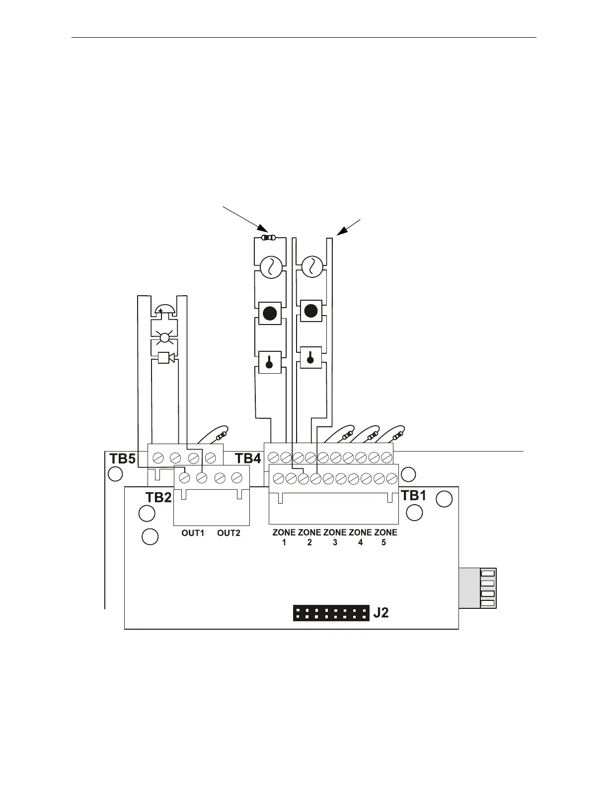
Wiring NACs and IDCs for Class A
Wire the Style Z (Class A) Notification Appliance Circuits using TB5 of the FACP main circuit
board and TB2 of the N-CAC-5X module. Wire the Style D (Class A) Initiating Device Circuits
using TB4 of the FACP main circuit board and TB1 of the N-CAC-5X. Note that the wiring will be
identical when using TB7 NAC and TB6 IDC of the FACP. Make certain to observe polarity when
connecting the devices to the circuits. The B+ and A+ terminals must comprise the feed and return
for the positive side of a device and the B- and A- terminals must comprise the feed and return for
the negative side of a device. To configure any of the zones for Class B when the N-CAC-5X is
installed, simply wire to the B+ and B- input on the FACP terminal(s) and install the End-of-Line
Resistor after the last device on the circuit. Do not wire to the corresponding A+ and A- terminals
on the N-CAC-5X module.
Figure 2.14 Wiring NACs and IDCs for Class A Operation
N-CAC-5X Class A Converter Module
FACP Main
Circuit Board
Class B (Style B) IDC - 4.7 KΩ
½ watt ELR resistor
P/N:71252 (supervised and power-limited)
Dummy load all unused
circuits - 4.7 KΩ
½ watt resistor
(P/N: 71245)
Polarized
Bell
Circuit polarities
shown in alarm
condition
Class A (Style Z) NAC
(supervised and power-limited)
Class A (Style D) IDC
(supervised and power-limited)
Polarized
Strobe
Polarized
Horn
Smoke
Smoke
Pull Station
Pull Station
Heat
Heat
ms10udclassa.cdr
B+ B- B+ B-
A+ A-
A+ A-
A+ A- A+ A- A+ A- A+ A- A+
B+ B- B+ B- B+ B- B+ B- B+

 Loading...


