26 RP-2002 Series Manual — P/N 53039:E6 1/26/2017
Installation Input Circuits
Combination Manual Release/Abort
A combination Manual Release/Abort circuit allows an FACP to distinguish between a manual
release pull station and an abort switch installed on the same circuit. Any circuit can be pro-
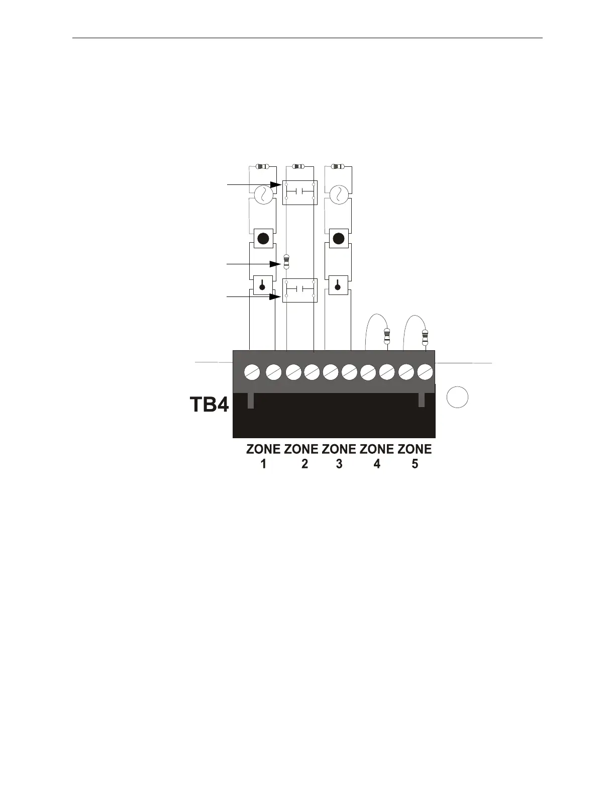
grammed as a Combo Type zone. The following figure illustrates the wiring of Zone 2 as a Style B
(Class B) Manual Release/Abort circuit.
Requirements for the Combination Manual Release/Abort circuit are as follows:
The manual release pull station must connect to the FACP Initiating Device Circuit before
the In-Line Resistor as shown in Figure 2.7.
The Abort Switch must connect to the FACP Initiating Device Circuit after the In-Line
Resistor as shown in Figure 2.7.
Program the FACP Initiating Device Circuit as a Manual Release/Abort combination circuit
as described in “Input Zones” on page 54.
Class B Initiating Device Circuits (supervised and power-limited)
4.7 KΩ, ½ watt resistor P/N:71252
In-Line-Resistor
1.2 KΩ, ½ watt resistor P/N: 75579
Manual release
pullstation
Dummy load all unused
circuits - 4.7 KΩ, ½ watt
resistor (P/N: 71245)
Figure 2.7 Style B Combination Circuit on Zone 2
Abort Switch
ms10udcomboIDC.cdr

 Loading...


