10
WARNING
For TurboLite Edge models (Galva-
nized cable with HeavyDuty Vectran/
Polyester Webbing portion for tie-
back installation): Set-back distance
must ensure that webbing portion of
the lifeline shall not contact an edge
during a fall.
3.5 Installation in a Lift Application
(Refer to Fig. F)
WARNING
When SRLPs are used in Aerial Lift
applications a Competent Person
shall advise if additional Fall Protec-
tion equipment must be used to mini-
mize the risk of user ejection from the
platform or basket. Failure to com-
plete this assessment may result in
serious injuries or death in a free fall
event. It’s not recommended to use
SelfRetracting Lifelines bigger than
SRLPs in any case.
Honeywell Safety Products recommends
mounting all Honeywell Miller Self-
Retracting Lifelines to a suitable overhead
anchorage whenever possible. However,
fall protection in lift applications without
an overhead anchorage requires special
provisions. The support structure of the lift
must meet the following criteria:
• Both the floor-level anchorage and
the guardrails must be capable of
supporting at least 5,000 lb (22,2kN)
per employee attached or be part of a
complete personal fall arrest system
which maintains a safety factor of at
least two, under the supervision of a
qualified person.
• The guardrails are at a height that
eliminates the possibility of a free
fall in the system (See standards for
construction: OSHA 1926.502 and
general industry: OSHA 1910.23.
• The diameter of the guardrail must be
a minimum of 1 inch (25,4mm).
• All edges that may come into contact
with the lifeline during use must be
smooth or rounded or chamfered (free
of burrs and sharp edges) to prohibit
damage to the lifeline and enable the
unit to arrest a fall effectively.
• The support structure must surround
the user in the direction of all
possible falls.
• The lift itself must be designed
properly to prevent toppling in
the event of a fall (consult the lift
manufacturer).
Honeywell recommends the above listed
SRL’s can be attached at or below the back
D-ring of the user’s harness in lift appli-
cations under the direction of a qualified
person. Since these units are not mounted
overhead in this application, the maximum
fall arrest forces may exceed the maximum
arresting force listed on the label; however,
the forces will not exceed 1,800 lbf (8kN).
The following should be considered when
assessing your application:
• The proper amount of fall clearance is
calculated from the top of the guardrail
using SRL guidelines provided in this
instruction manual.
• Ensure no swing-fall hazard exists.
• Lifeline contact with sharp edges
must be avoided.
• Preventative measures must be taken
to ensure the SRL does not become
pinched between two surfaces as this
may cause excessive lifeline wear and
weakness.
Please contact Honeywell Technical
Service at 8008735242 (press 4) for
additional assistance when evaluating this
installation application.
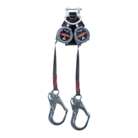
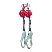
3.6 Twin Turbo G2 (See TABLE 1)
The Twin Turbo G2 Connector is designed
for use by ONE person only. Maximum
capacity is 420 lb (190.5 kg), combined
tool and body weight. — DO NOT EXCEED
THIS WEIGHT.
TABLE 1: Miller Twin Turbo G2 Connector
MODEL NO. DESCRIPTION MATERIAL WEIGHT
MFLC/ Twin Turbo G2 Connector
with harness D-pad clip
Aluminum, nylon plastic 6 oz. (0.23kg) - G2
Connector w/webbing
retainer clip0.67 oz
(0.03kg) - optional D-pad
clip

 Loading...
