11
Use only Honeywell-approved compatible
personal fall limiters/SelfRetracting
Lifelines with this device. Never attach
snap hooks, rebar hooks or carabiners to
the G2 Connector.
Always verify that the connector gate
is completely closed and locked. While
the Twin Turbo G2 System is designed
to provide a user with two connecting
devices for continuous 100% tie-off fall
protection, it is important to note that both
PFLs should only be connected at the
same time when transitioning from one
anchorage to another. During the normal
course of work, only one of the PFLs
should be connected to the anchorage.
To retain 100% tie-off, one PFLs must be
connected to an anchorage at all times.
WARNING
The G2 Connector must be thoroughly
inspected and operationally tested
Confirm proper operation of the connec-
tor gate. The gate of the connector should
seat into the nose without binding and
should not be distorted or obstructed. The
gate spring should exert sufficient force
to firmly close the gate. The gate locking
mechanism must prevent the gate from
opening when closed.
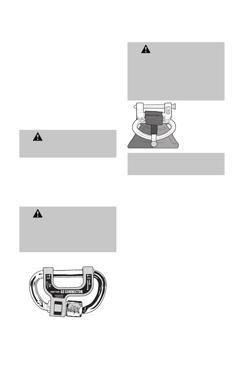
WARNING
When Twin Turbo G2 Connector is
properly installed, harness webbing
MUST be captured in connector cara-
biner and webbing retainer clip. This
does not apply for H700 harness.
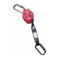
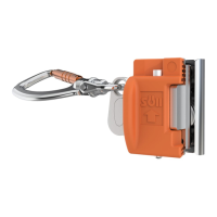
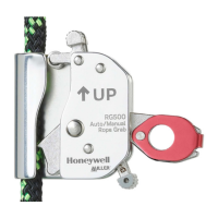
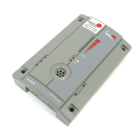
3.7 TurboLite Flash Personal Fall
Limiters with QuickConnect
Harness Connector.
WARNING
All Honeywell Miller SelfRetracting
Lifelines must be inspected and
tested for locking and retraction
before each use (See 5.0 Inspection
& Maintenance). The installer of the
SRL must not be exposed to a fall
hazard while mounting the unit.
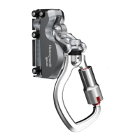
QuickConnect
Harness
connector (Refer
to Fig C3C10 for
use instructions.)
IMPORTANT: While reading the
installation / use instructions, refer to
referenced pictures on pages 4041
3.8 Horizontal Use
When installing a SelfRetracting Lifelines
for horizontal use, special considerations
and warnings apply.
The following should be considered when
mounting SRLPs for horizontal use:
• Only use TurboLite Edge (ANSI Class
2) models due to the likelihood of
contact with sharp edges in this
application
• Free fall distance may exceed 6ft
• Increased swing fall potential
• The locking speed of the SRL may
vary in the event of a fall due to
friction between the lifeline and the
platform edge
• The SRL may lock up quicker than the
workers walking pace and thus cause
a fall by jerking the worker off balance
4.0 Calculating Fall Clearance
Distance
It is essential to understand how to
calculate the fall clearance distance
required for each work application to
avoid contact with a lower level.
The basic calculation shown below and the
related figures on page 45 may be used to
determine Required Fall Clearance when
 Loading...