Do you have a question about the Honeywell ML6420 and is the answer not in the manual?
| Brand | Honeywell |
|---|---|
| Model | ML6420 |
| Category | Controller |
| Language | English |
Describes ML6420 actuators used with controllers providing switched or floating SPDT output for HVAC.
Describes ML7420 actuators used with controllers providing analog output for HVAC applications.
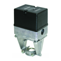
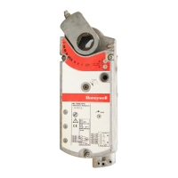
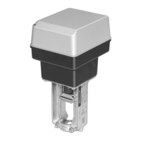
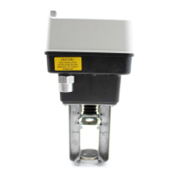
Details the ML6420A and ML7420A actuator models and their basic descriptions.
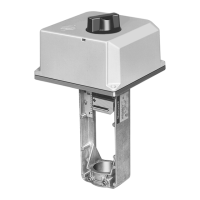
Refers to Figure 1 for approximate physical dimensions of the actuators.
Specifies the weight of the actuators as 2.9 lb (1.3 kg).
Details power input, consumption, signal source output resistance, and signal load.
Provides temperature and humidity limits for ambient, storage, and valve medium.
Specifies the stem force capability of the actuators as 135 lbf (600N).
Describes signal inputs for ML6420 (24 Vac) and ML7420 (0-10 Vdc or 2-10 Vdc).
Lists materials for cover, base, and yoke of the actuator.
Specifies the actuator stroke length as 3/4 in. (20 mm).
Refers to Table 1 for close-off pressure ratings with various Honeywell valves.
Indicates the ingress protection rating as IP54.
Lists certifications including CSA, UL, and CE requirements.
Details optional accessories like high temperature kits and auxiliary switches/potentiometers.
Provides contact information and website for purchasing and obtaining product details.
Emphasizes reading instructions, checking ratings, and using trained technicians.
Advises installing the actuator where there is adequate clearance for mounting and servicing.
Step-by-step guide for physically attaching the actuator to the valve.
Instructions for feeding wires through the conduit connector and making connections.
Illustrates the typical wiring hookup for the ML6420 actuator.
Highlights electrical shock and equipment damage hazards during wiring.
Shows wiring for ML7420 using feedback output from a controller with a common transformer.
Details wiring for ML7420 using a 4 to 20 mA control signal and separate transformers.
Illustrates wiring for ML7420 using a 2 to 10 Vdc control signal and separate transformers.
Shows the location of W1, W2, and W3 selector plugs for ML7420 configuration.
Explains how the synchronous motor converts rotary motion to linear stem motion.
Instructions for manually opening or closing the valve using the operator knob.
Describes how to set the analog input signal range for the ML7420.
Explains how the ML7420 can be set to a specific position during signal failure.
Details the analog output signal (2 to 10 Vdc) representing actual stem position.
Explains how to override the control signal for freeze protection or other applications.
Procedure for checking actuator operation without a controller, ensuring proper mounting and wiring.
Procedure for checking actuator operation using a controller, verifying setpoint response and wiring.





 Loading...