ML7421A,B ELECTRIC LINEAR VALVE ACTUATOR
63-2517—1
4
CAUTION
Do not install actuator in a position below horizontal to
minimize risk of damage to the actuator in the event of
condensation or a valve gland leak.
Mounting
NOTE: Check valve body literature for valve stem button
adjustment dimension.
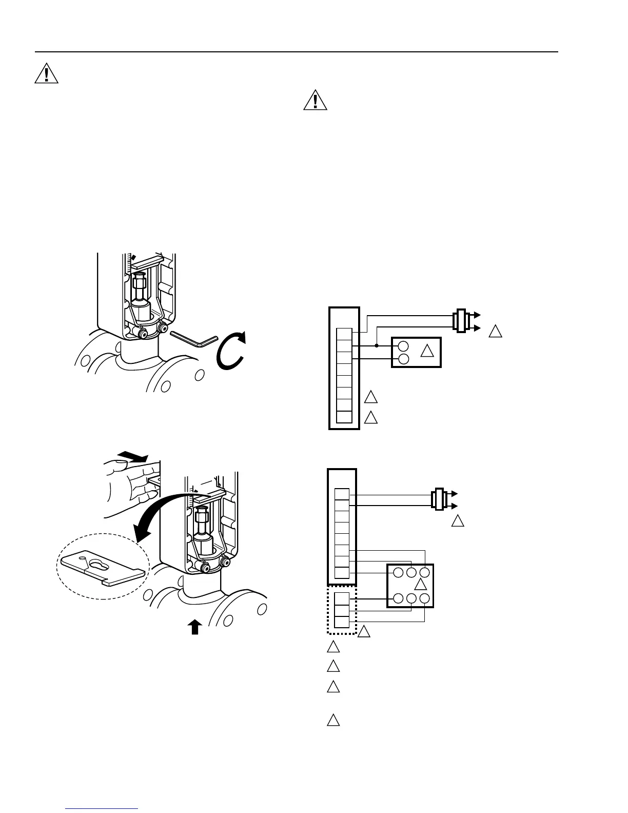
A Attach the actuator to the valve collar and tighten the
set screws with a 5/32 in. (4 mm) hex wrench.
IMPORTANT
When tightening the set screws, first tighten the right
set screw. See Fig. 2.
M6639
TIGHTEN RIGHT
SET SCREW FIRST
Fig. 2. Attaching actuator to valve collar.
B Push in the stem button retaining clip and hold. See
Fig. 3.
M6638
Fig. 3. Attaching actuator to valve stem.
C Lift the valve stem until the head of the valve stem
button is inside the large slot of the stem button
retaining clip on the actuator.
D Release the stem button retaining clip to secure the
stem button.
E Check to ensure that retaining clip holds the stem
button in place.
F Pull off the manual operation knob, loosen the cover
screws, and remove the actuator cover.
Wiring
CAUTION
Disconnect power supply before wiring to prevent
electrical shock or equipment damage.
All wiring must comply with local electrical codes, ordinances,
and regulations. Voltage and frequency of the transformer
used with the ML7421 must correspond with the
characteristics of the power supply and those of the actuator.
A Feed the power and control wires through the opening
on the bottom of the actuator case.
B Using the wiring diagrams in Fig. 4 through 9, connect
the power and control wires to the ML7421. Make sure
that all wiring is correct.
C When wiring and checkout are complete, replace the
cover, tighten the cover screws, and replace the
manual operator knob, Fig. 10.
D Apply power and control signals to the ML7421.
Fig. 4. ML7421 typical wiring diagram.
WIRING
STRIP
T1
T2
+
O1
O2
R1
W1
B1
1
L1
(HOT)
L2
–
+
OUTPUT
ML7421A,B
2
POWER SUPPLY. PROVIDE DISCONNECT MEANS
AND OVERLOAD PROTECTION AS REQUIRED.
0 TO 10 OR 2 TO 10 VDC CONTROL SIGNAL
(DEPENDING ON ACTUATOR MODEL).
1
2
M6745
Fig. 5. ML7421 with 0 to 135 ohm input wiring diagram.
WIRING
STRIP
T1
T2
+
O1
O2
R1
W1
B1
1
L1
(HOT)
L2
ML7421A,B
2
POWER SUPPLY. PROVIDE DISCONNECT MEANS AND OVERLOAD
PROTECTION AS REQUIRED.
SERIES 90 SLIDE-WIRE CONTROLLER. OUTPUT IS R-W-B AND INPUT
(FOR FEEDBACK SIGNAL) IS T-Y-G.
TERMINALS: T, Y, AND G DO NOT APPEAR ON THE WIRING BLOCK,
OR EVEN ON ALL MODELS, BECAUSE THEY ARE FOR THE OPTIONAL
FEEDBACK POTENTIOMETER (POTENTIOMETER WIRING BLOCKS
ARE INCLUDED WITH THE POTENTIOMETER ASSEMBLY).
CODING SWITCH J1-J2 MUST BE OPEN. SEE SIGNAL INPUT
FAILURE SECTION.
1
2
M6746
T
T
Y
Y
G
G
B
WR
3
4
3

 Loading...


