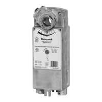
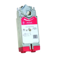
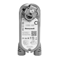
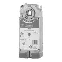
MS4104, MS4109, MS4604, MS4609, MS8104, MS8109 FAST-ACTING, TWO-POSITION ACTUATORS
5 63-2740—02
Installation
Device Malfunction Hazard.
Improper set screw tightening causes device
malfunction.
Tighten set screws with proper torque to prevent
damper shaft slippage.
Actuator Damage Hazard.
Using actuator as shaft bearing causes device
damage.
Use actuator only to supply rotational torque. Avoid any
side loads to actuator output coupling bearings.
To install actuator, proceed as follows:
1. Place actuator over damper shaft; and hold mounting
bracket in place. See Fig. 2.
2. Mark screw holes on damper housing.
3. Remove actuator and mounting bracket.
4. Drill or center-punch holes for mounting screws (or use
no.10 self-tapping sheet metal screws).
5. Turn damper blades to desired normal (closed) position.
6. Place actuator and mounting bracket back into position
and secure bracket to damper box with sheet metal
screws.
7. Tighten set screws securely into damper shaft using min-
imum 100 lb-in., maximum 130 lb-in. torque. Use
1/4 in. wrench (see Specifications for details) to tighten
set screws.
Wiring
See Fig. 3 through 5 for typical wiring diagrams.
Electrical Power Hazard.
Line voltage can cause death or serious injury and
short equipment circuitry.
Disconnect power supply before installation.
Electrical Shock or Equipment Damage Hazard.
Low voltage can shock individuals or short
equipment circuitry.
Disconnect power supply before installation.
IMPORTANT
1. All wiring must comply with local electrical codes,
ordinances and regulations.
2. Voltage and frequency of transformer must corre-
spond with the characteristics of power supply and
actuator.
3. Use wires rated for at least 75°C (167°F).
4. The conduit fittings are designed for use with 3/8 in.
reduced-wall steel or aluminum flexible conduit.
Fig. 3. Typical 24 Vac wiring.
Fig. 4. Typical 120 Vac wiring.
Fig. 5. Typical 230 Vac wiring.
M34624
24 VAC
BLACK
RED
L1
( )
L2
( )
YELLOW
YELLOW
BLUE
7° AUXILIARY
SWITCH
85° AUXILIARY
SWITCH
BLUE
WHITE
BLACK
GREEN
L1
( )
L2
( )
YELLOW
YELLOW
BLUE
BLUE
7° AUXILIARY
SWITCH
85° AUXILIARY
SWITCH
120 VAC
M34625
M34626
BLUE
BROWN
GREEN
230 VAC
L1
( )
L2
( )
YELLOW
YELLOW
BLUE
BLUE
7° AUXILIARY
SWITCH
85° AUXILIARY
SWITCH