16 www.honeywell.com
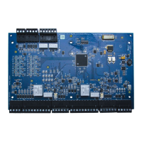
Installing the PRO4200 Two Reader Module
Power
Power
The Two-Reader Module accepts 12VDC with an operating range of 10 to 14VDC
and consumes a maximum of 300mA of current without readers. Locate power source
as close to this board as possible. Connect power with minimum of 18 AWG wire.The
input voltage is regulated to 5VDC.The regulated voltage or the 12VDC (pass
through) is available for powering the readers. The selection is made via jumpers and
is available at both reader connectors.
Note: POLARITY for 12VDC power is important. Make sure the +12 VDC is connected to
the terminal labeled +12V and the return is connected to the terminal labeled GND.
Communications
The Two-Reader Module communicates to the host controller via an RS-485
interface.The interface allows for multi-drop communication of up to 4,000 feet
D6 Input1
D7 Input 2
D8 Input 3
D9 Input 4
D10 Input 5
D11 Input 6
D12 Input 7
D13 Tampert
D14 Power
D15 Relay 0 status
D16 Relay 3 sttatus
D17 Relay 2 status
D18 Relay 4 status
D19 Relay 1 status
D20 Relay 5 status
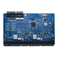
Table 3: Additional PRO4200 Two Reader Module LEDs
LED number Description
 Loading...
