Do you have a question about the Honeywell PW7K1R2 and is the answer not in the manual?
Critical safety and operational warnings for installation and use.
Procedures for handling and shipping the module, including damage claims.
Overview of the module's features, capabilities, and technical specifications.
Guide to setting up jumpers and DIP switches for module configuration.
Detailed instructions for reader, input, and output wiring.
Options and step-by-step guide for physically installing the module.
Configuration details for RS485 port and reader connections.
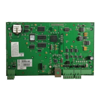
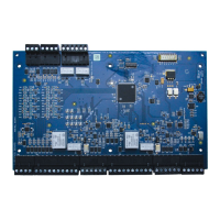
The Honeywell Pro-Watch 7000 Two-Reader Module (PW7K1R2) is designed to support up to two access control doors, offering a comprehensive solution for managing access points within a security system. This module facilitates connections for various reader types, including Wiegand or Clock/Data, and integrates with supervised inputs and relay outputs to provide robust access control capabilities.
The module's design allows for flexible installation, either rack-mounted or flat-mounted. When rack-mounted, one edge of the board is accessible for wiring, optimizing space in a rack enclosure. A flat-mount configuration, while potentially decreasing the number of boards that can be mounted in a single enclosure, increases the amount of available I/O.
The I/O terminals are logically organized to support two doors. The rack-mount side of the board features connectors for power, communication with the Intelligent Controller (PW7K1IC or PW6K1IC), and terminals for reader 1. These include inputs for Door Status and REX status, and relay outputs for Door Lock and Lock Status. Further up this edge, additional connectors are provided for reader 0 and its associated I/O terminals. The last connector on the rack-mount edge offers terminals for two general-purpose inputs.
For flat-mount installations, the module provides additional functionalities, including two extra relay outputs and two general-purpose inputs. Dedicated inputs for cabinet tamper and power fault detection are also available on the opposite edge of the board in this configuration.
The reader interface is versatile, accepting both Wiegand (Data 1 and Data 0) and Clock and Data signals. It provides selectable 5VDC or 12VDC power to the readers, along with tri-stated LED control and buzzer control. Six form-C relay outputs are integrated into the module. Two of these relays are specifically sized for the inductive loads of door locks, while the remaining four are designed for dry-circuit signals. All inputs, except for the two dedicated inputs, are capable of four-state supervision, enhancing security and monitoring capabilities.
Communication with the control panel is established via an RS-485 interface, supporting multi-drop communication over distances up to 4,000 feet (1,200 m). The default communication speed is 38.4Kbps, with options to downgrade to 19.2Kbps or 9.6Kbps if line conditions or receiving equipment require it.
A key feature of the Pro-Watch 7000 module is its ability to grant access based on facility code even when communication to the control panel is lost. In such scenarios, general-purpose outputs will retain their last setting. The module can support up to eight active facility codes in each PW7K1R2 or PW6K1R2. Keypad input is also supported, following the reader input format and either replacing or multiplexing with the reader data.
The module incorporates onboard LEDs (D1 and D2) to provide status information during power-up and normal operation. D1 and D2 indicate the power-up sequence (hardware setup, RAM testing, ROM testing, and initialization completion). During normal operation, D1 serves as a processor heartbeat LED, flashing once per second. A short ON time indicates the board is offline or has lost serial communication with the Controller board, while a long ON time signifies that the board is online and communicating. D2 flashes to indicate activity on its Serial Port.
In addition to the status LEDs, there are six relay status LEDs and eight input status LEDs. Input LEDs flash when a fault is associated with the input. When a relay or input is energized or ON, its corresponding status LED illuminates and remains ON for the duration of the energized state.
The module accepts 12VDC power within an operating range of 10 to 14VDC. It consumes 300 mA of current without readers. Power connections should be made with a minimum of 18AWG wire, and polarity for 12VDC power is crucial, with +12VDC connected to the +12V terminal and return to the GND terminal. The input voltage is regulated to 5VDC, which, along with the 12VDC pass-through, is available for powering readers, with selection made via jumpers at both reader connectors.
For RS-485 communication, specific wiring practices are recommended: TR+ for the positive differential signal, TR- for the negative differential signal, and GND for the signal ground. The GND connection is required and must not be connected to chassis GND. Use 24 AWG low capacitance, two twisted-pair, shielded cable (e.g., Belden 9842). When daisy-chaining RS-485 ports, TR+ and TR- wires from upstream and downstream boards should be connected to the respective terminals. A jumper (J1) is provided for bus termination; it should be closed if the module is the last board on the RS-485 bus.
Reader wiring supports various Honeywell reader module numbers. Each reader port has a TTL interface, with reader power selectable between 5VDC and 12VDC via jumpers J2 (for reader 0) and J3 (for reader 1). The factory default for J2 and J3 is 5V. A 6-conductor 18AWG cable is required for full reader port utilization. The LED control terminal can be configured via host software to support single-wire single or bi-colored reader LEDs. If Beeper Control is not used, its terminal can be programmed as the second wire for a two-wire bi-colored reader LED.
Inputs 0 to 7 can be configured for normally open or normally closed contacts, and for non-supervised or supervised operation (with 1K ohm end-of-line resistors). Inputs 0, 1, 2, and 3 have default functional definitions as Door Status and REX inputs for readers 0 and 1, respectively. Inputs 4, 5, 6, and 7 are general-purpose inputs for monitoring sensors or control. Inputs 6 and 7 are not accessible when rack-mounted. Inputs TMP (Tamper) and PFL (Power Fault) are typically used for cabinet tamper and power failure monitoring, especially in remote flat-mount installations. These inputs are unsupervised and not accessible when rack-mounted. Input configuration, including debounce and hold time, is managed via host software.
Control output wiring provides six form-C relay contacts for controlling door strikes or other devices. These relays can be assigned to door-related functions or general-purpose outputs and are configurable as standard (energize to activate) or fail-safe (de-energize to activate) via host software. The energized or ON time of each relay can be configured using Pulse control for single or repeating pulses, with single pulses extendable up to 24 hours and repeating pulses defined in 0.1-second increments up to 255 times. Relays 0 and 2 are rated for and typically control door locks. To minimize premature contact failure and increase system reliability when switching inductive loads, a contact protection circuit is highly recommended and should be located close to the load. Relays 1 and 3 are dry-circuit level signal relays for indicating door lock status. Relays 4 and 5 are general-purpose relay outputs and are not available when rack-mounted. Sufficiently large gauge wires should be used for load current to prevent voltage loss.
Installation involves setting jumpers and DIP switches, mounting the board in the appropriate enclosure (component side to the right when rack-mounted), and connecting the communications and power supply using the Power Supply Harness. It is crucial not to connect the power supply to the AC socket until all wiring is installed and rechecked. Subsequent steps include connecting reader interfaces, input sensors (or installing jumper wires), relay output wiring, and communications wiring to the Intelligent Controller. After rechecking all wiring, the power supply cord can be connected, and panel controls set up using the host software.
| Reader Ports | 2 |
|---|---|
| Communication | RS-485 |
| Compatibility | Pro-Watch |
| Operating Temperature | 0°C to 50°C |
| Power Supply | 12 VDC |
| Voltage | 12 VDC |
| Display | No |
| Temperature Range | 0°C to 50°C |
| Dimensions | 6 in H x 4 in W x 1 in D (152 mm H x 102 mm W x 25 mm D) |