PW-7000 Two-Reader Module Installation Guide, Document 800-25676V1 17
Reader Wiring
The following Honeywell reader module numbers have been approved by UL for
use with the PW7K1R2: OM40BHONA, OM55BHONA, OP10HONE, OP30HONE,
OP40HONE, OP90HONE, OT30HONA, OT31HONA, OT35HONA, and OT36HONA.
Each reader port supports a reader with TTL interface. Power to the reader is
selectable as 5VDC or 12VDC (pass-through). This selection is done by setting the
jumpers J2 for reader 0 and J3 for reader 1. Set jumper at position "5" for 5VDC or
"12" for pass-through 12VDC. The factory defaults set J2 and J3 to "5".
For wiring to a reader port:
Table 5: Settings for Wiring to a Reader Port
The LED control terminal in each reader port can be configured via host software
to support one-wire single or bi-colored reader LED. An example of the most com-
mon configuration is shown below. If Beeper Control is not used, its terminal can
be programmed to be the second wire for the two-wire bi-colored reader LED.
Table 6: Settings for Configuring an LED Control Terminal
To fully utilize each reader port, a 6-conductor cable (18AWG) is required. Reader
port configuration is set via host software.
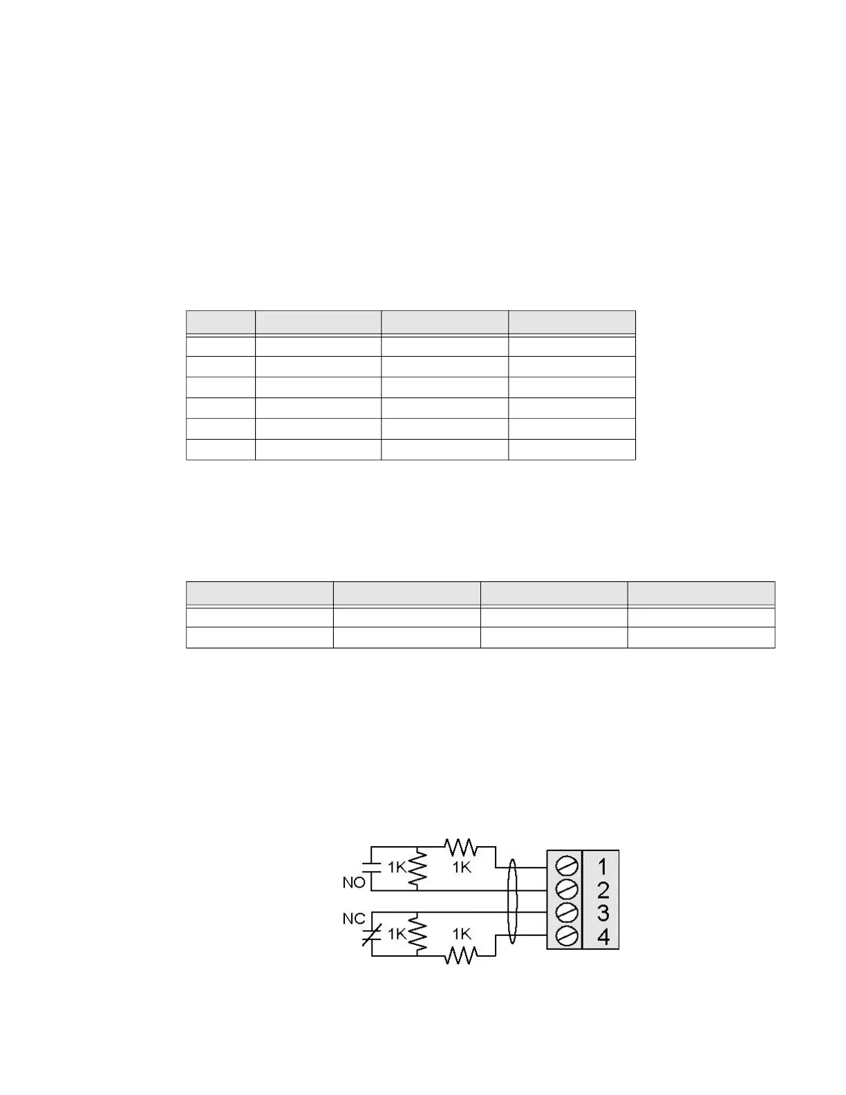
Input Wiring
Inputs 0 to 7 may be configured to use normally open or normally closed contacts
and non-supervised or supervised (with standard ±1% tolerance 1K ohm). Four of
these inputs have default functional definitions, but all eight can be configured to
monitor general-purpose sensors.
Terminal Typical Wire Color Wiegand Reader Clock/Data Reader
1
Red Power (5 or 12 Vdc) Power (5 or 12 Vdc)
2
Brown LED control LED control
3
Yellow Beeper Control Beeper Control
4
White Data 1 Signal Clock Signal
5
Green Data 0 Signal Data Signal
6
Black Common Common
LED Output-> High Tri-Stated Low
Single Color LED
LED On LED Off LED Off
Bi-Color LED
Green LED On Both LEDs Off Red LED On
 Loading...