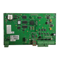
PW-7000 Two-Reader Module Installation Guide, Document 800-25676V1 13
Table 4: Additional PW7000 Two-Reader Module LEDs
Power
The Two-Reader Module accepts 12VDC with an operating range of 10 to 14VDC
and consumes 300 mA of current without readers. Locate power source as close to
this board as possible. Connect power with minimum of 18AWG wire.The input volt-
age is regulated to 5VDC.The regulated voltage or the 12VDC (pass through) is
available for powering the readers. The selection is made via jumpers and is avail-
able at both reader connectors.
Note: POLARITY for 12VDC power is important. Make sure the +12 VDC is connected to the
terminal labeled +12V and the return is connected to the terminal labeled GND.
Communications
The Two-Reader Module communicates to the host controller via an RS-485 inter-
face. The interface allows for multi-drop communication of up to 4,000 feet (1,200
m) total per port. Use two twisted pair (minimum 24AWG) with shield for communi-
cation. The default speed of this port is 38.4Kbps but it can be downgraded to
19.2Kbps or 9.6Kbps if the line conditions or receiving equipment require it (see
Table 1: Jumper Settings (page 11) for jumper settings and Table 2: DIP Switch
Settings (page 11) for DIP switch settings).
For wiring to an RS-485 port:
LED number Description
D3
Reader 0 activity
D4
Reader 1 activity
D5
Input 0
D6
Input 1
D7
Input 2
D8
Input 3
D9
Input 4
D10
Input 5
D11
Input 6
D12
Input 7
D13
Tamper
D14
Power
D15
Relay 0 status
D16
Relay 3 status
D17
Relay 2 status
D18
Relay 4 status
D19
Relay 1 status
D20
Relay 5 status
 Loading...