14 PW-7000 Two-Reader Module Installation Guide, Document 800-25676V1
Step 1. TR+ is the plus side of the transmit and receive differential signal.
Step 2. TR- is the negative side of the transmit and receive differential signal.
Step 3. GND is the signal ground.The wiring for this signal is required and NOT
optional. This signal must NOT be connected to chassis GND.
Step 4. Use 24 AWG low capacitance, two twisted-pair, shielded cable (Belden
9842 or equivalent).
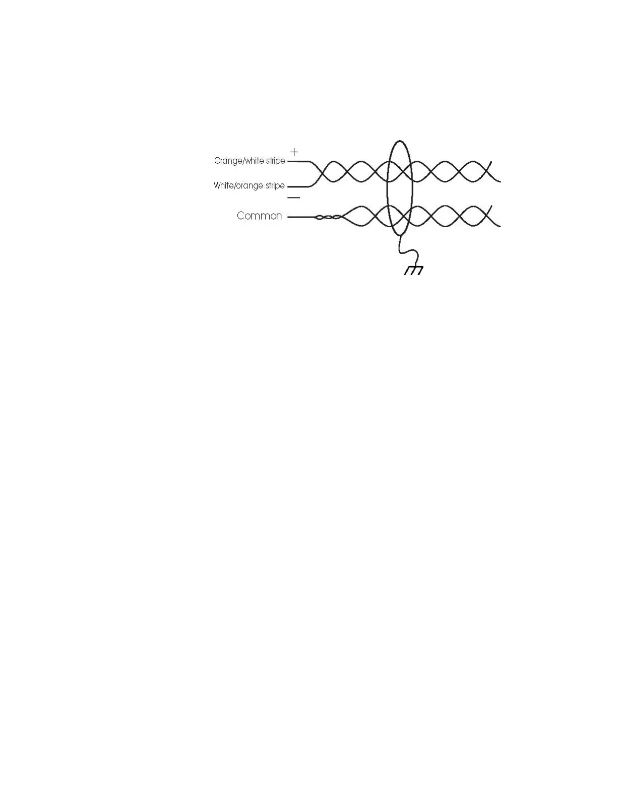
Note: For RS-485 Communication Connections, twist the blue pair together and use as the
common; use the orange pair as your data pair, observing polarity. Connect the
external drain shield to the appropriate earth ground on one end.
Step 5. When daisy-chaining RS-485 ports together, connect the TR+ wires from
the upstream and downstream boards to the TR+ terminal. Likewise,
connect the TR- wires from the upstream and downstream boards to the
TR- terminal.
By factory default J1 is set open. If this board is the last board on the RS-485 bus,
install jumper J1 across both pins (closed). Closing J1 provides the bus termina-
tion required.
Wiring
This section presents information on reader wiring, input wiring, and control out-
put wiring. The following figure shows the PW-7000 board and identifies its termi-
nal block pin assignments.
 Loading...