12 PW-7000 Two-Reader Module Installation Guide, Document 800-25676V1
* = Default
LED Operation
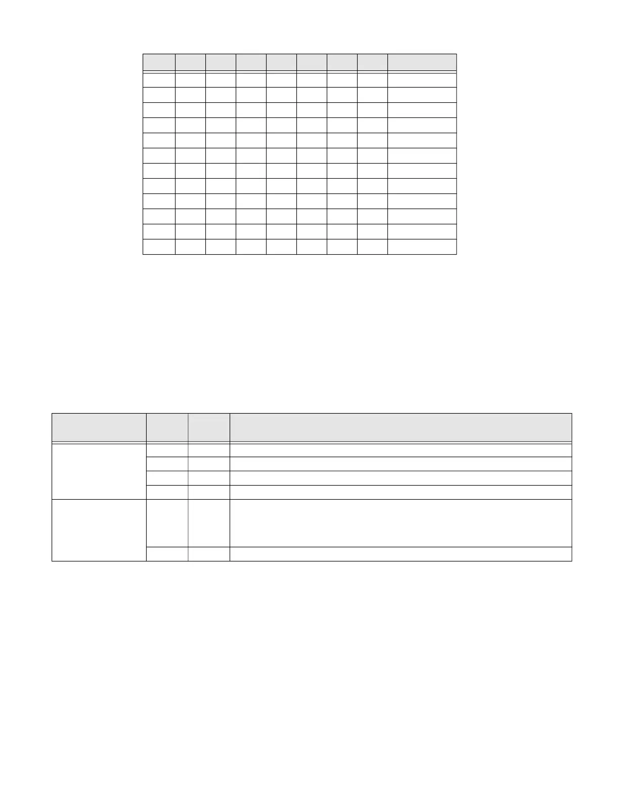
The Two-Reader Module uses two onboard LEDs (D1 and D2) to provide status
information during the power-up sequence as well as during normal operation. The
Two-Reader Module also uses two onboard LEDs (D3 and D4) to indicate reader
activity.
Table 3: Onboard LEDs
In addition to the status LEDs, there are six additional relay status LEDs and eight
input status LEDs on board. The input LEDs flash when there is a fault associated
with the input. When any relay or input is energized or ON, its corresponding status
LED becomes ON also. The LED remains ON for as long as the relay is energized.
The assignment for each relay status LED is shown in the following table.
ON ON OFF OFF ON ADDRESS 25
ON ON OFF ON OFF ADDRESS 26
ON ON OFF ON ON ADDRESS 27
ON ON ON OFF OFF ADDRESS 28
ON ON ON OFF ON ADDRESS 29
ON ON ON ON OFF ADDRESS 30
ON ON ON ON ON ADDRESS 31
OFF OFF Reserved
OFF ON 9,600 BPS
ON OFF 19,200 BPS
ON ON 38,400 BPS*
OFF
Not Used*
S8 S7 S6 S5 S4 S3 S2 S1 Selection
Mode
LED
D1
LED
D2
Description
Power-up
sequence
ON OFF Start power-up, hardware setup.
OFF ON Testing RAM.
ON ON Testing ROM and completing initialization.
FLASH ON LED D1 flashes four times after power-up is completed.
Normal Opera-
tion
FLASH This is the processor heartbeat LED. It flashes once every second. A short ON
time (~20% duty cycle) indicates the board is offline or has lost serial
communication with the Controller board. A long ON time (~80% duty cycle)
indicates the board is online and communicating with the Controller board.
FLASH Flash when there is activity on its Serial Port.
 Loading...