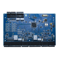
The Honeywell PRO4200 Two Reader Module (PRO42R2) is an access control device designed to support up to two doors. It offers connections for Wiegand or Clock/Data type readers, supervised inputs, and relay outputs. The module can be mounted either in a rack or flat, with rack mounting providing access to one edge for wiring, while flat mounting offers slightly more I/O but reduces the number of boards that can be housed in a single enclosure.
The I/O terminals are organized to facilitate connections for two doors. On the rack-mount side, the bottom connector supplies power to the board and enables communication with the Intelligent Controller (PRO42IC and PRO32IC). Moving upwards, the next set of terminals connects Reader 2, followed by the I/O typically associated with Reader 2, including Door Status and REX status inputs, and Door Lock and Lock Status relay outputs. Further up, two more connectors provide the reader and associated I/O terminals for Reader 1. The topmost connector on this edge offers terminals for two additional general-purpose inputs.
When the board is mounted flat, two extra relay outputs and two additional general-purpose inputs become available, along with two dedicated inputs for cabinet tamper and power fault detection on the opposite edge of the board.
The reader interface supports Wiegand (Data 1 and Data 0) or Clock and Data signals, providing selectable 5VDC or 12VDC reader power, tri-stated LED control, and buzzer control. Two of the six form-C relay outputs are designed for the inductive loads of door locks, while the remaining four are for dry-circuit signals. All inputs, except the two dedicated ones, are capable of four-state supervision.
Communication with the control panel is established via an RS-485 interface. The board requires a 12VDC input power supply. In the event of communication loss with the control panel, the board can still grant access based on facility code only. General purpose outputs will maintain their last setting. Up to eight facility codes can be active in each PRO32IC and PRO42IC. Keypad input follows the reader input format and is multiplexed with the reader data.
Technical Specifications:
- Primary Power: 12VDC + 10%, 650mA maximum (with 5V readers), 300mA maximum (excluding readers).
- Relay Contacts:
- Relays 0-1: Form-C, 5A @ 30VDC, resistive.
- Relays 2-5: Form-C, 2A @ 30VDC, resistive.
- Inputs:
- 8 supervised inputs with End of Line resistors (1k ohm ± 1% tolerance).
- 2 unsupervised dedicated inputs.
- Communication: RS-485, range 9,600 to 38,400 bps.
- Wire Requirements:
- Power: 1 twisted pair, 18AWG (Honeywell 3114 or equivalent).
- RS-485: 24 AWG, 4,000 feet (1,200 m) max., twisted pair with shield (120Ω, 23pF) (Honeywell 3328 or equivalent).
- Inputs: 1 twisted pair per input, 30 ohms max.
- Outputs: As required for the load.
- Readers: 6 conductors, 18AWG, 500 feet (150m) max., shield and drain.
- Mechanical:
- Dimensions: 5.5" (140 mm) W x 9" (229 mm) L x 1" (25 mm) H.
- Weight: 12 oz. (340 g) nominal.
- Environment:
- Operating Temperature: 0°C to +49°C.
- Storage Temperature: -55°C to +85°C.
- Humidity: 0% to 85% RHNC.
Usage Features:
- Flexible Reader Support: Each reader port supports TTL (D1/D0, Clock/Data), F/2F, or 2-wire RS-485 signaling readers. Power to the reader is selectable between 5VDC and 12VDC via jumpers (J2 for Reader 1, J3 for Reader 2).
- Configurable Inputs: Inputs 0 to 7 can be configured as normally open or normally closed contacts, and as non-supervised or supervised (with standard ±1% tolerance 1K ohm). Inputs 0 and 1 are defaulted as Door Status and REX for Reader 1, respectively, while Inputs 2 and 3 serve the same functions for Reader 2. Inputs 4, 5, 6, and 7 are general-purpose. Inputs 6 and 7 are not accessible in rack-mount configurations.
- Dedicated Inputs: TMP (Tamper) and PFL (Power Fail) inputs are provided for monitoring cabinet tamper and power failure, particularly when the board is mounted remotely. These are unsupervised and not accessible in rack-mount.
- Control Output Wiring: Six form-C relay contacts can be assigned to door-related functions or general-purpose outputs. They are configurable as standard (energize to activate) or fail-safe (de-energize to activate) via host software. Relays 0 and 2 are rated for door locks associated with readers 0 and 1, respectively, and are the only ones approved for UL installations for door hardware.
- Pulse Control: The energized or ON time of each relay can be configured using Pulse control for single or repeating pulses via host software. Single pulses can be extended up to 24 hours, and repeating pulses can have on/off times defined in 0.1-second increments, repeated up to 255 times.
- LED Operation: Onboard LEDs (D1, D2) indicate power-up sequence and normal operation status. D1 flashes four times after power-up. D2 acts as a processor heartbeat LED, flashing once per second; a short ON time indicates offline status or lost serial communication, while a long ON time indicates online and communicating. D2 also flashes with serial port activity. Additional LEDs (D3-D20) indicate reader activity, input faults, and relay status.
Maintenance Features:
- Troubleshooting with LEDs: The various LEDs provide visual cues for diagnosing power-up issues, communication status, reader activity, and input/relay faults, simplifying troubleshooting.
- Return Authorization (RMA): For equipment returns, a Return Authorization Number (RMA) is required, obtained by contacting customer service. This streamlines the process for warranty service, repair, credit, or exchange.
- Packaging Retention: Users are advised to retain original packaging materials for potential reshipment, ensuring safe transport if the equipment needs to be returned.
- Warranty: Honeywell provides a two-year warranty on products from the date of shipment, limited to repair or replacement of defective products under normal use. A 90-day warranty applies to Terminals, Printers, Communications Products, and Upgrade kits.
- ESD Protection: Cautions are provided regarding electrostatic discharge (ESD) to prevent damage to CMOS integrated circuits and modules. Users are instructed to use static shield packaging and handle components at an approved static-controlled workstation.
- Contact Protection for Relays: To minimize premature contact failure and increase system reliability, a contact protection circuit is highly recommended for inductive loads (e.g., door strikes), to be located as close to the load as possible.
- Regular System Testing: Installers are advised to test the system regularly and instruct end-users on daily testing procedures to ensure proper functioning and avoid liability.