Installing the PRO4200 Two Reader Module
Wiring
PRO4200 Two-reader module User Guide, Document 800-25698V1 17
(1,200 m) total per port. Use two twisted pair (minimum 24 AWG) with shield for
communication. The default speed of this port is 38.4Kbps but it can be downgraded
to 19.2Kbps or 9.6Kbps if the line conditions or receiving equipment require it (see
Table 1 on page 3 for jumper settings and Table 2 on page 4 for DIP switch settings).
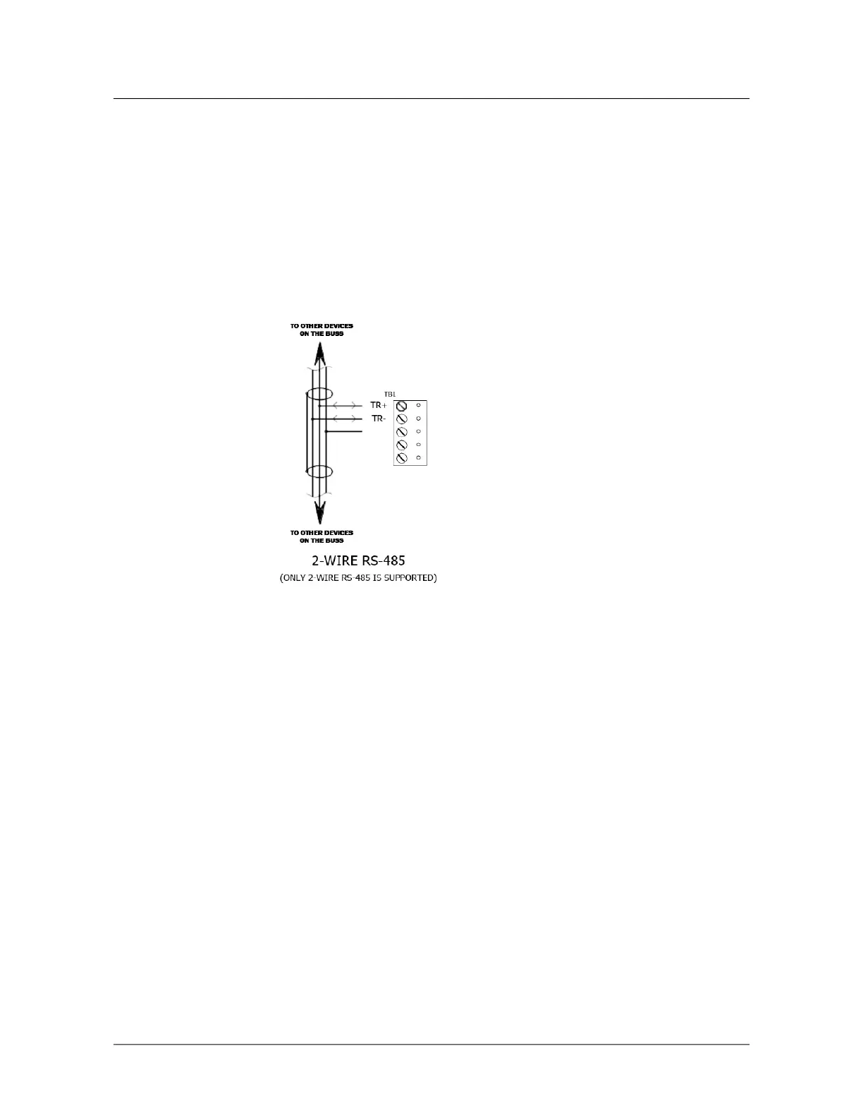
For wiring to an RS-485 port:
1. TR+ is the plus side of the transmit and receive differential signal.
2. TR- is the negative side of the transmit and receive differential signal.
3. GND is the signal ground.The wiring for this signal is required and NOT optional.
This signal must NOT be connected to chassis GND.
4. Use 24 AWG low capacitance, two twisted-pair, shielded cable (Honeywell 3328 or
equivalent).
Note: For RS-485 Communication Connections, twist the blue pair together and use as
the common; use the orange pair as your data pair, observing polarity. Connect the
external drain shield to the appropriate earth ground on one end.
1. When daisy-chaining RS-485 ports together, connect the TR+ wires from the
upstream and downstream boards to the TR+ terminal. Likewise, connect the
TR- wires from the upstream and downstream boards to the TR- terminal.
By factory default J1 is set open. If this board is the last board on the RS-485 bus,
install jumper J1 across both pins (closed). Closing J1 provides the bus termination
required.
Wiring
This section presents information on reader wiring, input wiring, and control output
wiring.
The following figure shows the PRO4200 board and identifies its terminal block pin
assignments
.
 Loading...