R4140G, L AND M FLAME SAFEGUARD PROGRAMMING CONTROLS
60-0770—2
25
The procedure in this step depends on the model of the
plug-in flame signal amplifier used.
a. All self-checking models:
R7247B Dynamic Self-Check Rectification
Amplifier (green)—used with rectifying flame
rods, rectifying photocells, or C7012A or C
Purple Peeper Ultraviolet Flame Detectors.
R7247C Dynamic Self-Check Rectification
Amplifier (green)—used with C7012E or F
Purple Peeper Ultraviolet Flame Detectors
(with self-checking shutter).
R7248B Dynamic Ampli-Check Infrared Amplifier
(red)—used with C7015A Infrared (lead
sulfide) Flame Detectors.
R7476A Dynamic Self-Check Ultraviolet Amplifier
(blue)—used with C7076A Adjustable
Sensitivity Ultraviolet Flame Detectors.
(1) Let the programmer complete its revolution
and open the master switch.
(2) Replace the plug-in amplifier with a new
one of the same part number.
(3) Wait a minute and reset the Lockout switch.
(4) Close the master switch to start the
programmer.
(5) When the pilot (or first stage burner) is
ignited, relay 2K should pull in.
(6) If relay 2K pulls in, operation is normal.
Omit steps and , and perform the Pilot
Turndown Test in the Checkout section
(unless using direct spark ignition).
(7) If relay 2K does not pull in, either the flame
detector or the programmer is faulty.
— Install the original amplifier.
— Check the flame detector and its
circuit as described in step .
— If the problem still exists, replace
the programmer.
b. All standard models (R7247A, R7248A, and
R7249A).
(1) Let the programmer complete its revolution.
(2) Close the manual pilot shutoff valve (or
manual first stage fuel valve if using direct
spark ignition).
(3) Open the master switch and remove the
programmer from the subbase.
(4) Remove the flame detector leadwire from
terminal F on the subbase. Be sure the
leadwire does not touch anything after
removal.
(5) Reinstall the programmer on the subbase
and reset the Lockout switch (if popped out).
(6) Set the Timer switch to the TEST position.
(7) Proceed to the following instructions for the
appropriate amplifier.
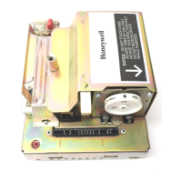
c. R7247A Rectification Amplifier (green)—used
with rectifying flame rods, rectifying photocells, or
C7012A or C Purple Peeper Ultraviolet Flame
Detectors.
(1) Complete step b. above.
(2) Close the master switch to start the
programmer. Wait until the timer stops.
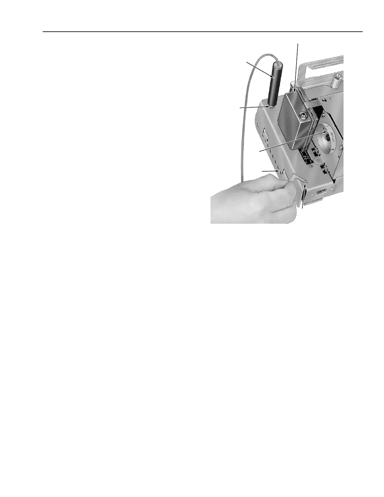
(3) Plug the probe of a 123514A Flame
Simulator into the tip jack on the front of the
programmer chassis (Fig. 13).
TIP JACK
PROGRAMMER
CHASSIS
TIMER
DIAL
HOLD PLUG END
AGAINST R4140
CHASSIS
R7247A (GREEN) OR
R7249A (PURPLE)
PLUG-IN AMPLIFIER
PLUG PROBE
INTO TIP JACK
ON R4140
CHASSIS
M7963
Fig. 13. Using flame simulator.
(4) Hold the plug (lead end) of the simulator
against the programmer chassis. Relay 2K
should pull in and stay in while the plug is
in contact with the chassis.
NOTE: As soon as 2K pulls in: on an R4140G
or M, relay 1K drops out and the timer
starts to run. On an R4140L, relay 3K
drops out and safety shutdown occurs in
about one-half minute.
(5) If relay 2K pulls in, the trouble is in the
flame detector or its circuitry outside the
programmer. Proceed to steps and .
(6) If relay 2K does not pull in, set the timer
switch to the NORM position, let the timer
complete its revolution, and open the
master switch.
(7) Replace the plug-in amplifier with a new
one of the same part number.
(8) Wait a minute and reset the Lockout switch.
(9) Set the timer switch to the TEST position.
(10) Close the master switch to start the
programmer.
(11) When the timer stops, repeat step (4).
(12) If relay 2K pulls in, restore the programmer
to operating condition as instructed in
step , below.
(13) If relay 2K still does not pull in, replace the
programmer.
 Loading...