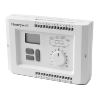
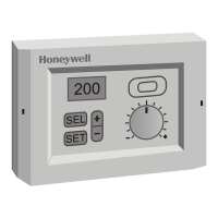
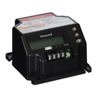
R7426A,B,C,D TEMPERATURE AND UNIVERSAL INPUT CONTROLLERS
3 63-2565
Approvals:
Protection class II.
NEMA 1, IP30 or (with front panel mounting
only
) IP40.
FCC Part 15, Class B.
Accessories:
43193862-001 Front panel mounting frame.
NTC 20K ohm sensors for CPATYP 3 (10 to 20K ohms):
C7031B1033: For duct discharge air, hot water.
C7031D1062: For hot or chilled water.
C7031F1018: For outdoor air temperature.
C7031J1050: For duct discharge air (averaging).
C7031K1017: For hot or chilled water (strap-on).
T7770A1006: Wall module with locking cover.
T7770B1004: Wall module with locking cover and setpoint
adjustment knob (55°F to 85°F).
Pt 1000 sensors for CPATYP 1:
C7031D1070: For hot or chilled water.
C7031F1026: For outdoor air temperature.
C7031J1068: For duct discharge air (averaging).
C7031K1025: For hot or chilled water (strap-on).
Table 1. CPA/SPA Selectable Inputs.
a
Default value.
Table 2. Sensor Offset Per 33 ft (10m) of Wire.
INSTALLATION
When Installing this Product...
1.
Read these instructions carefully. Failure to follow them
could damage the product or cause a hazardous
condition.
2.
Check the ratings given in the instructions and on the
product to make sure the product is suitable for your
application.
3.
Installer must be a trained, experienced service
technician.
4.
After installation is complete, check out product operation
as provided in these instructions.
Mounting
The controller can be mounted in an electric cabinet or other
suitable enclosure. They are suitable for back panel, wall, and
DIN rail mounting.
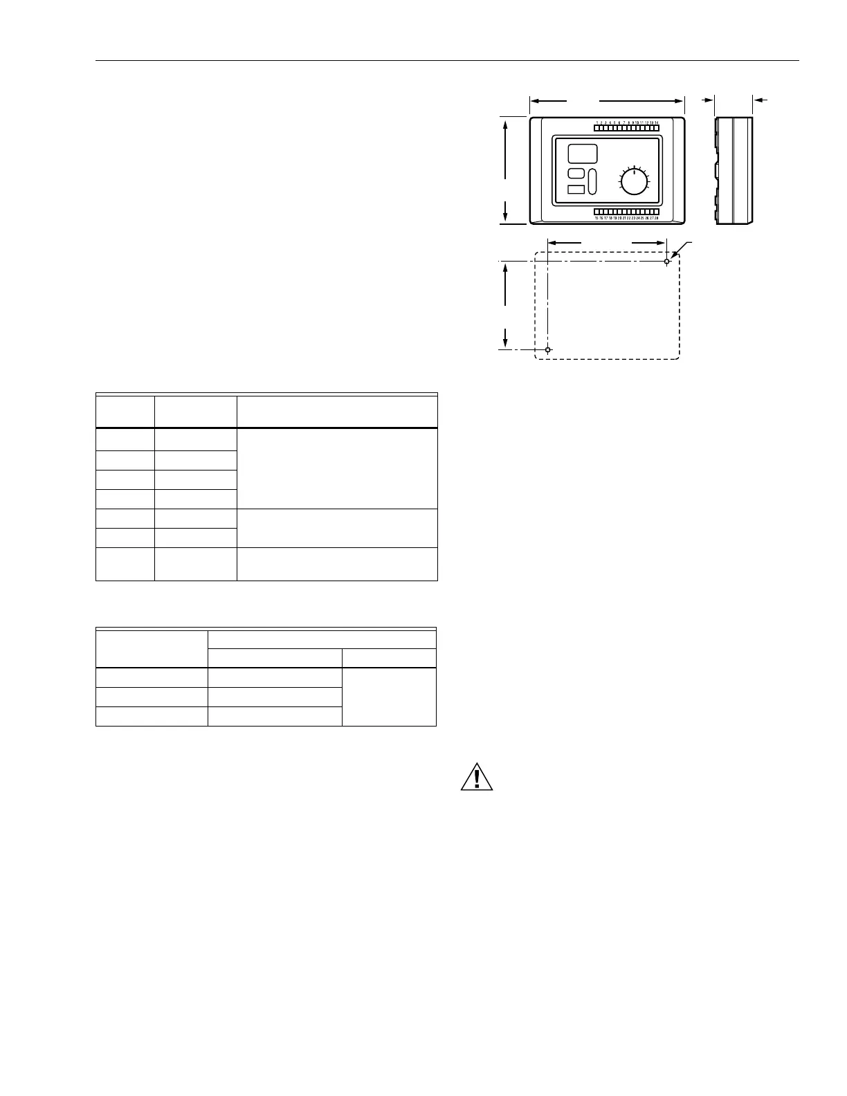
Fig. 1. R7426 Dimensions.
Back Panel or Wall Mounting
1.
Drill two holes in the mounting surface (see Fig. 1).
2.
Remove the controller from the baseplate:
a. Insert a flat head screwdriver into the slot at the right
side of the control face.
b. Pull control right side slightly away from baseplate.
c. Insert a flat head screwdriver into the slot at the left
side of the control face.
d. Pull the controller away from the baseplate.
3.
Mount the baseplate to the surface.
4.
Replace the controller on the baseplate.
DIN Rail Mounting
1.
Remove the controller from the baseplate:
a. Insert a flat head screwdriver into the slot at the right
side of the control face.
b. Pull control right side slightly away from baseplate.
c. Insert a flat head screwdriver into the slot at the left
side of the control face.
d. Pull the controller away from the baseplate.
2.
Mount the baseplate to the TS35 DIN rail.
3.
Replace the controller on the baseplate.
Wiring
Electrical Shock or Equipment Damage Hazard.
Can shock individuals or short equipment
circuitry.
Disconnect power supply before installation.
IMPORTANT
All wiring must agree with applicable codes,
ordinances and regulations.
Connect the wires to the device:
1.
Strip 3/8 in. to 1/2 in. of insulation from the controller
end of each wire.
2.
Insert each wire into the appropriate terminal on the top
or bottom of the device (see Fig. 2 and 3):
a. Solid wire: Push stripped end into terminal.
b. Stranded wire: Apply pressure to numbered indent
corresponding to the terminal while inserting wire.
3.
Apply power to the device.
CPATYP
Value
Sensor
(in ohms) CPA/SPA range
0
a
internal CPA: ±9°F
1 9574 to 1426
2 100K to 0
4 0 to 10K
3 9574 to1426 SPA: 59°F to 86°F (15°C to 30°C)
5 0 to 100K
6 0 to 100K SPA: 32°F to 122°F (0°C to 50°C)
or 32°F to 266°F (0°C to 130°C).
Wire Type
in AWG (mm
2
)
Temperature offset in °F (°C)
Pt 1000 NTC
20 (0.5) 0.32 (0.18) negligible
17 (1.0) 0.16 (0.09)
15 (1.5) 0.11 (0.06)
+
–
SEL
SET
4-1/8
(105)
3-7/16
(87)
1-7/16
(37)
6 (152)
4-5/8 (118)
1/8 (3) DIAMETER
WALL MOUNTING
M17411
 Loading...