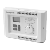
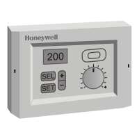
R7426A,B,C,D TEMPERATURE AND UNIVERSAL INPUT CONTROLLERS
15 63-2565
Fig. 11. Step change responses of proportional,
P+I, and P+I+D controls.
Start Point: O
start
(P.15)
O
start
determines the output O1 midrange shift from the
calculated control point.
R7426A,B,C
O
start
is available on the single output R7426A and the
R7426B when the three floating outputs are configured for
6-stage On/Off sequence control.
Calibrate O
start
in degrees Fahrenheit. It is equal to the offset
(plus or minus) from the set values or calculated control points
at which O1 is at 50 percent.
NOTE: In P+l control, the start point should be set at zero.
R7426D
Calibrate O
start
in percent. It represents deviation from the
control point.
In humidification and dehumidification control, O
start
must be
decreased by 50 percent of the throttling range (Xp1).
EXAMPLE:
• Set OCTRF to 1 for reverse control behavior.
• Set Xp1 at 6 percent.
• Set O
start
at -3 percent.
With these settings:
— If the actual humidity value is equal to the calculated
control point CTRP1 (zero deviation), the humidifier
valve will be fully closed.
— At 6 percent rh below CTRP1 the valve is fully open.
— At 6 percent rh above CTRP1, the controller provides
an output signal of +1200 mV (100 percent) to fully
open the cooling valve for dehumidification.
NOTE: Always set O
start
to the value for proportional
control.
Occupied/Unoccupied Function: SOFFS (P.16)
A potential free contact can be used between terminals 1 and
4 to switch between occupied (contact closed) and
unoccupied (contact open) modes.
Control point calculation:
• Occupied mode: Use temperature setpoint (W1).
• Unoccupied mode: SOFFS parameter value is added to
(cooling) or subtracted from (heating) the calculated control
point.
• Heating and cooling sequence applications: SOFFS value
is added to the control point for cooling (CTRPC) and
subtracted from the control point for heating (CTRPH). See
Fig. 12.
IMPORTANT
Set the R7426A parameter Dir/RevO1 to Dir or Rev
to match the required heating or cooling application.
If parameter Dir/RevO1 is set to Cho (summer/winter
changeover), parameter SOFFS is ignored.
Fig. 12. Sequence control occupied/unoccupied function.
For control point calculation and reference to applications, see
Table 15. Using the table, you can construct the equation to
use for calculating the proper control point.
EXAMPLE:To calculate CNTRPC for temperature cascade
sequence, use Table 15 to construct the formula:
Table 15. Control Point Reference and Calculation
a
Control with Heating, Mixed Air Dampers, or Energy
Recovery and Cooling
M17453
Xw
Xw (%)
(%)
O
0
TIME
TIME
tr
P + I + D CONTROL
P
P
tr
P + I CONTROL
PROPORTIONAL CONTROL
P=
100
Xp
(%/S)
Xw (%)
O
TIME
tr
td
P
P
tr
P=
P x v
d
100
Xp
(%/S)
Main Temperature
Cascade
Temperature
Sequence
a
Temperature
Cascade
Sequence
a
CNTRP1
CNTRPC
CNTRPH
CNTRP2
CNTRPC
CNTRPH
W1 + + + +
XOFFS + +
CPA + + + +
OAT
comp
++++
W
cas
++++
SOFFS +- +-
R
cas
/100 x
(Omaster+50)
----
XP1 / 2 + -
XP2 / 2 + -
O(%)
T
100
M17454
OFFS OFFS
CTRPH CTRP1
UNOCCUPIED
OCCUPIED
XpH XpC
 Loading...
