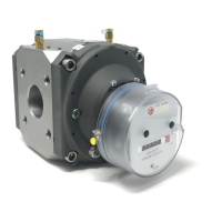
The Honeywell RABO® rotary gas meter (Type RABO® G16 – G400) is a volume-measuring device designed for gaseous media, operating on the positive displacement principle. Its volumetric measuring principle ensures that its functioning is not influenced by installation conditions, making it ideal for compact measuring systems without requiring an inlet section. The meter records gas volume at operating conditions and is approved for custody transfer applications. For volume conversion, electronic volume conversion devices can be used.
Function Description:
The meter's core mechanism involves two rotating impellers, shaped like a figure-of-eight in cross-section, housed within a single body with one inlet and one outlet. These impellers are coupled by synchronizing gears. As gas flows through the meter, the impellers rotate without metallic contact, propelling a defined volume of gas to the outlet with each cycle. One complete rotation of the system corresponds to a specific gas volume. The rotational movement of the impellers is then reduced by a gear train and transmitted to a mechanical index via a magnetic coupler. Fine adjustment of the rotary gas meter is achieved using a pair of gears within the index.
Important Technical Specifications:
- Size: G16 to G400
- Nominal Size: DN 32 to DN 150
- Operating Pressure: Max. 20 bar
- Gas Temperature: -25°C to +70°C
- Housing Material: Available in Aluminium or Spheroidal Graphite Iron
- Protection Class: IP67
- Measured Media: Natural gas and various filtered, non-caustic gases. It is suitable for flammable gases (natural gas/propane/butane) and non-flammable gases (air/nitrogen/inert gases). The hydrogen content in gas mixtures must not exceed 10%. The product is not intended for aggressive gases like biogas, sewage gases, oxygen, or acetylene.
- Metrological Accuracy Class: AC 1.0
- Error Limits (according to EN 12480):
- ±1.0% for Qt to Qmax
- ±2.0% for Qmin to Qt
- Ambient Temperature: -25°C to +70°C
- Storage Temperature: -40°C to +70°C
- Humidity: 0 to 80% RH
- Max. Height above Sea Level: 2000 m
- Outdoor Installation: Yes
- Mechanical Environments: M1
- Approvals: MID (DE-12-MI002-PTB001), PED (CE-0085CN0022), ATEX (II 2G Ex h IIC T4 Gb, 557/Ex-Ab 2664/16), IECEx (Ex h IIC T4 Gb, IECEx TUR 16.0042X).
Usage Features:
- Installation Position and Flow Direction: The RABO® meter can be installed for both horizontal and vertical gas flow. Crucially, the impeller shafts and the digit rollers on the index must always be horizontally aligned. The index can be rotated up to 355° for optimal readability in various installation and operating positions. If the installation or operating position is specified at the time of order, all attachments will be factory-fitted accordingly. For subsequent vertical installation, the index and any other attachments (e.g., volume conversion devices) must be rotated by 90°. Honeywell Customer Service Centre assistance is recommended for such conversions.
- Temperature Test Points: Up to two temperature sensors can be used to measure gas temperature within the meter housing. If no internal test points are provided, external temperature measurements should be taken in the pipe downstream of the gas meter, at a distance of up to 3 x DN, but no more than 600 mm away. For optimal thermal conduction, thermowells should be filled with a heat-conductive fluid or paste.
- Pressure Test Points: A straight male coupling conforming to DIN 2353 is provided on the meter housing (marked pm/pr) for connecting pressure sensors. It is designed for Ø 6 mm steel tubes (DIN EN 10305-1, e.g., steel grade E235) or flexible pressure tubes from Honeywell. Functional safety is ensured only if the union component and pipe materials are intermatched. Stainless steel or non-ferrous pipes should not be connected to this coupling. Only original Parker-Ermeto pipe unions should be used.
- Pulse Generators/Encoders: The meter can be fitted with low-frequency (LF) pulse generators (Elster GmbH IN-Sxx, IN-Cxx, Sxx-Rx) and high-frequency (HF) pulse generators (Pepperl & Fuchs SJ2-N), as well as Elster GmbH ENCODER S1. Separate instruction manuals provide further details on these devices.
- SxD Index: Indexes S1D and S2D feature two roller indexes. A hinged plate covers one index and indicates the flow direction, which can be changed by unscrewing two front screws, folding the plate down, and resecuring it.
- Oil Filling: The meter must be filled with oil (Shell Morlina S2 BL 10 or Molyduval Chemlube 315) before commissioning. The filling quantity varies by meter size and flow direction (e.g., G16 to G100: 25 ml horizontal, 100 ml vertical; G160 to G400: 25 ml horizontal, 150 ml vertical). The meter must be depressurized for oil filling. The oil level is correct when visible in the threads of the inspection borehole or in the center of the inspection window.
- Commissioning: The system should be filled slowly until operating pressure is reached, with a pressure rise not exceeding 350 mbar/s. A bypass line (recommended 12 mm pipe diameter) should be used for filling. The measuring range of the gas meter must not be exceeded, even briefly. A tightness test must be performed after commissioning.
- Protection: A cone strainer with a mesh size of 250 µm is recommended to protect the meter. For vertical installations with upward flow, strainers should be fitted at both the inlet and outlet. These strainers should be removed after 4-6 weeks to prevent flow inhibition due to saturation.
Maintenance Features:
- Routine Maintenance: After commissioning, the measuring instrument does not require special maintenance or oil-level inspections. The oil should be replaced after a maximum of 5 years.
- Cleaning: Only a damp cloth should be used for cleaning to avoid electrostatic discharge. Cleaning the plastic cover of the index with a dry cloth poses an explosion risk. Aggressive chemical cleaning agents or solvents are prohibited.
- Repair/Removal: Maintenance work should only be performed when the gas pipe is depressurized. Repairs must be carried out by authorized workshops.
- Decommissioning: Slowly reduce gas pipe pressure (max. 350 mbar/s) and ensure the pipe is depressurized. Undo screw connections and remove the meter. Drain the oil from the meter using the oil drain sleeve.
- Disposal: The meter consists mainly of metallic materials suitable for recycling in steelworks and metallurgical plants. Plastics used are listed in Annex B to facilitate sorting and separation for recycling. The supplied mineral oil must be disposed of in an environmentally sound manner.