Do you have a question about the Honeywell RABO G65 and is the answer not in the manual?
Details the intended applications and limitations for Elster RABO Rotary Meters.
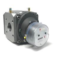
Explains the positive displacement mechanism used by the RABO meter for gas measurement.
Illustrates horizontal and vertical installation options for RABO meters.
Step-by-step instructions for adding lubricating oil to the meter's index.
Outlines the procedure for safely taking the meter out of service and removing it.
Recommends periodic inspections and routine maintenance tasks for RABO meters.
Describes methods for testing meter accuracy and performance.
Explains the process of proving meter accuracy against a traceable reference.
Lists performance metrics like rangeability, start rate, and stop rate for RABO meters.
Provides a chart to select the appropriate RABO meter model based on flow rate and pressure.
Lists physical dimensions and weights for standard RABO meter models.
Details calculating instantaneous flow rate using the meter's test dial.
Provides steps for removing, installing, and replacing the meter's index assembly.
Lists technical specifications for IN-S10 and IN-S10A pulsers.
Shows wiring connections for IN-S11 and IN-S12 pulser models.
Detailed steps for installing an instrument drive on a CTR meter.
Instructions for assembling the change gear to the ID magnet holder for different meter sizes.
Steps to attach the ID magnet holder and gearing assembly to the meter.
Procedure for mounting the ID adaptor plate assembly to the meter.
Guidance on reorienting the instrument drive assembly for different flow directions.
| Supply voltage | 230 Vac |
|---|---|
| Accuracy | N/A (Proving system, not direct measurement) |
| Resolution | N/A (Proving system, not direct measurement) |
| Operating Humidity | Max. 95% r.H., non-condensing |
| Power Supply | 230 Vac |