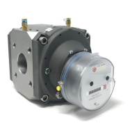
RABO
®
Rotary
Gas
Meter
Table of
Contents
1. General Information 3
2. Intended Use and Application 3
3. Operating Principle 3
4. Receiving, Handling and Storage 4
5. Installation 4
6. Start-up/Commissioning 6
7. Decommissioning and Removal 6
8. Inspection and Maintenance 6
9. Testing 6
10. Technical Data 8
11. Index 12
12. Pulser 14
13. Thermowell 15
14. Instrument Drive (ID) 15
15. Auxiliary Equipment Mounting 17
16. Direct mount TCI or EC350 18
17. Troubleshooting 19
1. General Information
T
h
i
s
m
a
nu
a
l
covers the
i
n
s
t
a
ll
a
t
i
on
,
o
p
e
r
a
t
i
on
and
m
a
i
n
t
e
n
a
n
c
e
f
o
r
the
E
l
s
t
e
r
I
n
s
t
r
o
m
e
t
RABO
R
o
t
a
r
y
Meter.
R
e
f
e
r
to
E
A
M
-
T
B
5900
f
o
r
a
dd
i
t
i
on
a
l
i
n
f
o
r
m
a
t
i
on
.
2.
I
n
t
e
n
d
e
d
Use and
A
pp
li
c
a
t
i
on
Elster RABO meters are suitable for measuring most types of
clean, dry, non-corrosive common gases. They are NOT
intended
f
o
r
use on
b
i
o
g
a
s
,
sewage
gas, oxygen,
a
c
e
ty
l
e
n
e
or
li
q
u
i
d
s
o
f
any
k
i
n
d
.
Product
li
f
e
and
m
e
a
s
u
r
e
m
e
n
t
accuracy
can be
a
ff
e
c
t
e
d
by
c
on
t
a
m
i
n
a
t
i
on
i
n
the gas stream.
P
e
r
i
o
d
i
c
s
e
r
v
i
c
i
n
g
will
p
r
o
l
on
g
the
li
f
e
and
p
e
r
f
o
r
m
a
n
c
e
o
f
the
m
e
t
e
r.
3. Operating Principle
T
h
e
RABO
meter
u
t
ili
z
e
s
p
o
s
i
t
i
v
e
d
i
s
p
l
a
c
e
m
e
n
t
p
r
i
n
c
i
p
l
e
o
f
o
p
e
r
a
t
i
on
w
h
i
c
h
makes
v
o
l
u
m
e
t
r
i
c
m
e
a
s
u
r
e
m
e
n
t
s
by
d
i
s
p
l
a
c
i
n
g
f
i
n
i
t
e
v
o
l
u
m
e
s
o
f
gas.
T
h
e
p
o
s
i
t
i
v
e
d
i
s
p
l
a
c
e
m
e
n
t
occurs w
i
t
h
i
n
a
c
a
v
i
ty
f
o
r
m
e
d
between the
m
e
t
e
r
’
s
i
n
t
e
r
n
a
l
hou
s
i
n
g
and
i
t
s
rotating impellers. The counter-rotating
“figure-
8”
impellers [Figure
1]
turn as a
r
e
s
u
l
t
o
f
pressure
drop across
the
m
e
t
e
r
’
s
i
n
l
e
t
a
n
d
ou
t
l
e
t
created as
d
o
w
n
s
t
r
e
a
m
gas
i
s
consumed.
T
h
e
r
o
t
a
t
i
n
g
impellers
separate
the flowing gas
into small, finite volumes and are counted using a mechanical
index. The
RABO
meter
has no wearing parts
because
precision
clearances between
the impellers and meter body
are maintained by timing
gears,
which are
designed
to
enhance
long term accuracy. Combining
adequate
filtration
and periodic
maintenance,
a
RABO
meter will remain accurate
over many
years.
As the
left
impeller
rotates
toward the
vertical
position, gas enters the
cavity
created
between the
impeller and the
housing.
When the
left
impeller
reaches
the vertical
position, a
finite
volume of gas is
captured in
the
left
cavity.
As the impellers continue
to turn, the volume of gas
in the
left cavity
is
discharged.
Simultaneously, gas is
entering the space
between
the right impeller
and
housing.
After
further rotation,
the
right impeller
becomes
vertical
and a
finite
volume of gas is
captured in
the
right
cavity.
Fi
g
u
r
e
1.
O
p
e
r
a
t
i
n
g
P
r
i
n
c
i
p
l
e

 Loading...