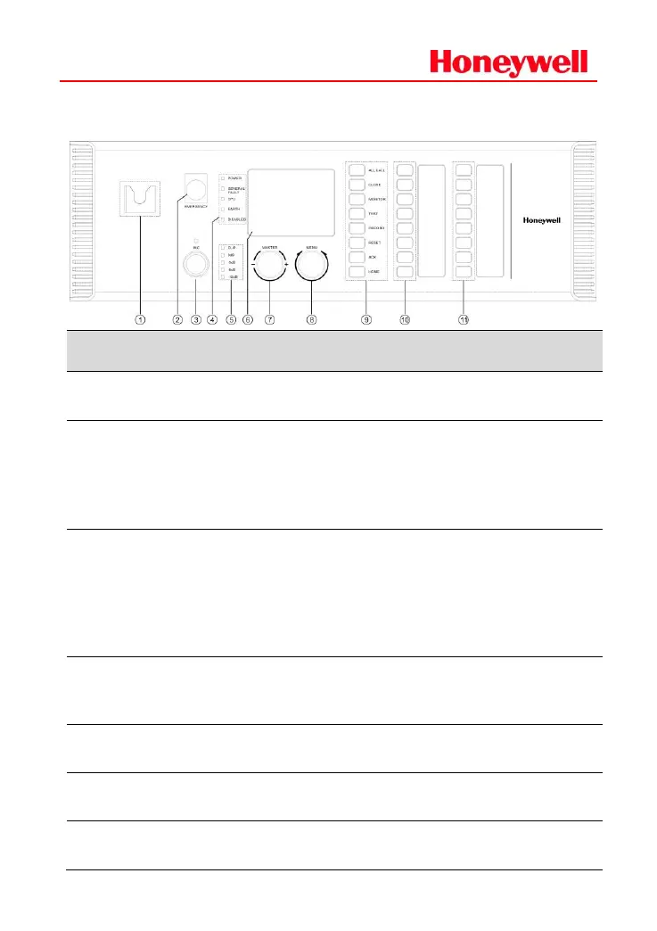
The microphone bracket is used for PTT
microphone.
A protective cover is above the emergency
button to avoid wrong operation.
If switching to manual emergency mode,
raise the protection cover, then press the
button. The indicator light turns red.
Microphone socket
and indicator light
The microphone socket is used to connect
PTT microphone to MCU.
The indicator light is off in standby mode.
When microphone is active, the light turns
green. When a fault is found, the light turns
orange.
Device status
indicator lights
To indicate status of device power, general
fault, CPU fault, ground fault, disabled status
etc.
To indicate the signal level of internal power
amplifier.
To display system work status and set the
parameters
Wheel knob of
master volume
To adjust the output volume of audio channel
1(BGM) in public address.

 Loading...