INSTALLATION INSTRUCTIONS
66-1085-04
SIL
3
Capable
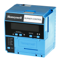
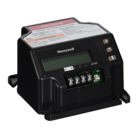
RM7800E,G,L,M; RM7840E,G,L,M
7800 SERIES Relay Modules
APPLICATION
The Honeywell RM7800/RM7840 Relay Modules are
microprocessor-based integrated burner controls for
automatically fired gas, oil, or combination fuel single burner
applications. The RM7800/RM7840 Relay Modules are used
for UL/CSA On/Off, UL/CSA Modulating, and FM/IRI
Modulating burner applications. The RM7800/RM7840 system
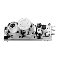
consists of a Relay Module. Keyboard Display Modules
(standard with RM7800), Dust Cover (standard with RM7840),
Subbase, Amplifier, and Purge Card. Options include DATA
CONTROLBUS MODULE™, Remote Display Mounting, First-
Out Expanded Annunciator and Communications through
Modbus™.
Functions provided by the RM7800/RM7840 include
automatic burner sequencing, flame supervision, system
status indication, system or self-diagnostics and
troubleshooting. The RM7800/RM7840 is a solid state
replacement for the electromechanical R4140 Automatic
Programming Control.
This document provides installation and static checkout
instructions. Other applicable publications are:
65-0084:Q7800A,B 22-Terminal Wiring Subbase Product
Data.
65-0089:ST7800A Plug-In Purge Timer Installation
Instructions.
65-0090:S7800A Keyboard Display Module Product Data.
65-0091:S7810A Data ControlBus Module™ Product Data.
65-0095:S7820 Remote Reset Module Product Data.
65-0097:221729C Dust Cover Packing Sheet.
65-0101:S7830 Expanded Annunciator Product Data.
65-0109:R7824, R7847, R7848, R7849, R7851, R7852,
R7861, R7886 Flame Amplifiers for the 7800 SERIES
Product Data.
65-0131:221818A Extension Cable Assembly Product
Data.
65-0229:7800 SERIES RELAY MODULES Checkout and
Troubleshooting Product Data.
65-0249:S7810M ModBus™ Module Product Data.
SPECIFICATIONS
Electrical Ratings, see Table 3:
Voltage and Frequency: 120 Vac (+10/-15%), 50 or 60 Hz
(±10%).
Power Dissipation: RM7800/RM7840: 10W maximum.
Maximum Total Connected Load: 2000 VA.
Fusing: 15A maximum, Type SC or equivalent Fast Blow.
Environmental Ratings:
Ambient Temperature:
Operating: -40°F to +140°F (-40°C to +60°C).
Storage: -40°F to +150°F (-40°C to +66°C).
Humidity: 85% relative humidity continuous, noncondensing.
Vibration: 0.5G environment.
SIL 3 Capable:
SIL 3 Capable in a properly designed Safety Instrumented
System. See form number 65-0312 for Certificate Agree-
ment.
Approvals:
Underwriters Laboratories Inc. Listed: File No. MP268,
Guide No. MCCZ.
Canadian Standards Association Certified: LR9S329-3.
Factory Mutual Approved: Report No. J.I.1V9A0.AF.
Swiss Re (formerly IRI): Acceptable.
Federal Communications Commission, Part 15,
Class B—Emissions.
INSTALLATION
When Installing this Product...
1. Read these instructions carefully. Failure to follow
them could damage the product or cause a hazardous
condition.
2. Check the ratings given in the instructions and marked
on the product to make sure the product is suitable for
the application.
3. Installer must be a trained, experienced, flame
safeguard service technician.
4. After installation is complete, check out the product
operation as provided in these instructions.
Fire or Explosion Hazard.
Can cause property damage, severe injury,
or death.
To prevent possible hazardous burner operation, verify
safety requirements each time a control is installed on
a burner.