RM7838B,C 7800 SERIES RELAY MODULE
32-00199—01 10
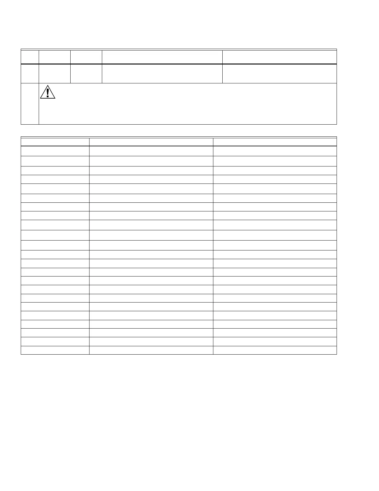
Table 4. Terminal Ratings.
a
See Table 2.
b
2000 VA maximum load connected to RM7838B,C Assembly.
c
See Tables 5 and 6.
14 13-15
(13-14 for
C1020)
None Adjust firing rate control and watch tracking
action of the firing rate motor.
1. Firing rate control.
2. Firing rate motor and transformer.
Final
Electrical Hazard.
Can cause equipment damage.
After completing these tests, open the Master Switch and remove all test jumpers from the subbase terminals.
Also remove bypass jumpers from the low fuel pressure limits if used.
Terminal No. Description Ratings
G
Flame Sensor Ground
a
—
Earth G
Earth Ground
a
—
L2 Line Voltage Common —
3 Alarm 120 Vac, 1A pilot duty.
4 Line Voltage Supply (L1)
120 Vac (+10/-15%), 50/60 Hz (+/-10%).
b
5 Combustion Blower 120 Vac, 9.8 AFL, 58.8 ALR (inrush).
6 Stop Input 120 Vac, 1 mA.
7 Lockout Interlock 120 Vac, 8A running, 43A inrush.
8Interrupted Pilot
120 Vac.
c
9Main Fuel Valve
120 Vac.
c
10 Ignition
120 Vac.
c
F(11) Flame Sensor 60 to 220 Vac, current limited.
12 Firing Rate High Fire 120 Vac, 75 VA pilot duty.
13 Firing Rate Common 120 Vac, 75 VA pilot duty.
14 Firing Rate Low Fire 120 Vac, 75 VA pilot duty.
15 Firing Rate Modulate 120 Vac, 75 VA pilot duty.
16 Pilot Valve Hold Input 120 Vac, 1 mA.
17 Manual Open Switch 120 Vac, 1 mA.
18 Low Fire Switch 120 Vac, 1 mA.
19 High Fire Switch 120 Vac, 1 mA.
20 Preignition Interlock 120 Vac, 1 mA.
21 Start Switch Input 120 Vac, 1A pilot duty.
22 Shutter 120 Vac, 0.5A.
Table 3. Static Checkout. (Continued)
Test
No.
Test
Jumpers Voltmeter Normal Operation
If Operation is Abnormal, Check These
Items
 Loading...