RM7838B, RM7838C 7800 SERIES RELAY MODULES
32-00211—01 12
D. MV1 is commanded to be open while MV2 remains
closed, to pressurize the space. After 4 seconds, MV1 is
commanded closed again.
E. This is followed by a three second delay, during
which the valve proving pressure switch (VPS) is
ignored.
F. Thereafter, the VPS is monitored for the duration of
the valve proving test time and, if it turns off, then a
lockout occurs. (Because the gas pressure has
decreased due to a leaky downstream valve.) (High
pressure test.)
Pressure Switches for Valve Proving
System
The Valve Proving System requires a pressure switch to be
installed to monitor the pressure in the internal space
between the two shutoff valves. Some recommended
pressure switches are the following Honeywell non-
manual reset models:
Table 7. Honeywell Pressure Switch Selection for Valve Proving System.
Pressure Switch Selection
1. Determine the maximum operating inlet pressure for
the upstream valve; for example, 5.0 psi (140 in. wc).
2. Divide the inlet pressure by two (2.5 psi [70 in. wc],
for example).
3.
From column 2 in Table 7 find the operating range
upper limit that is closest to but greater than the inlet
pressure divided by two. In the example given, the
possible selections from column 1 are the
C6097A1129 and C6097A1137 with an operating
range upper limit of 7 psi. (The C6097A1079 and
C6097A1087 with an upper limit of 60 in. wc are
close, but 60 in. wc is less than the 70 in. wc mini-
mum, so the next higher range must be selected.)
4. From column 6, select the preferred mounting type,
1/4 in. NPT or Flange. For example, if a flange mount
is required, the pressure switch choice from column
1 would be the C6097A1137.
Pressure Switch Installation and
Adjustment
1. Refer to the instructions for the C6097A Pressure
Switch, form number 65-0237.
2. Install the C6097A Pressure Switch according to the
instructions.
3. Adjust the setpoint to 50% of the maximum operat-
ing inlet pressure for the upstream valve.
4. Complete the operation and checkout procedures in
the instructions.
Setup of Valve Proving Function
Prior to setup of the Valve Proving Function, follow the
procedures in the appendix to complete the worksheet
and obtain the Valve Proving Test Time.
An S7800A1142 Keyboard Display Module (KDM) is
required for this setup and the RM7838 must have the
Valve Proving function.
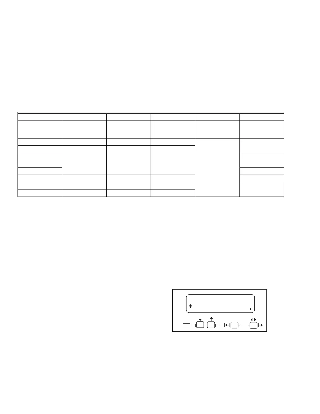
When the RM7838 is installed and powered, “STANDBY”
will be shown on the first line of the display.
1. Scroll down until the “Setup” is displayed in the sec-
ond line. (Setup is only available when the control is
in Standby or Lockout state.)
Fig. 6. STANDBY/Setup screen.
2. Enter the Setup submenu by pressing the far right
key on the display. Note that the second line now
reads “BC Password”.
123456
Model Number
Operating
Pressure Range
Maximum
Differential
(Additive)
Maximum
Continuous Rated
Pressure (psi)
Switch Action at
Setpoint Mounting Type
C6097A1004 0.4 to 5 in. wc 0.24 in. wc 2.9 Breaks N.O. to C
connection on
pressure fall.
1/4 in. NPT
C6097A1053 3 to 21 in. wc 0.48 in. wc 5.0
C6097A1061 Flange
C6097A1079 12 to 60 in. wc 2.4 in. wc 1/4 in. NPT
C6097A1087 Flange
C6097A1129 1.5 to 7 psi 0.3 psi 9.3 1/4 in. NPT
C6097A1137 Flange
C6097A1210 0.4 to 4 in. wc 0.24 in. wc 2.9
STANDBY
Setup
M22662B
BACK
ENTER
Edit:
-+