RM7838B, RM7838C 7800 SERIES RELAY MODULES
32-00211—01 4
Relay Module and Subbase
Compatiblity
NOTE: There are several different subbase models that
can be purchased. It is important to note which
subbase is compatible with the relay module
when purchasing new, repair or replacement
parts.
Series 1000 Relay Modules
All relay product codes that start with a 1 (example:
RM7840G1
014/U) can be used with existing subbase
Q7800A1003/U and Q7800A1005/U.
Series 2000 Relay Modules
All relay product codes that start with a 2 (example:
RM7840G2
014/U) must be used with subbase
Q7800A2003/U and Q7800A2005/U.
Subbase Compatibility
Any Relay Module in the 1000 Series with a Software
Revision level number starting with a "5" or greater will be
compatible with all subbase models both installed and
newly purchased. This includes (Q7800A1005/U,
Q7800B1003/U), and the 2000 Series subbases
(Q7800A2005/U, Q7800B2003/U).
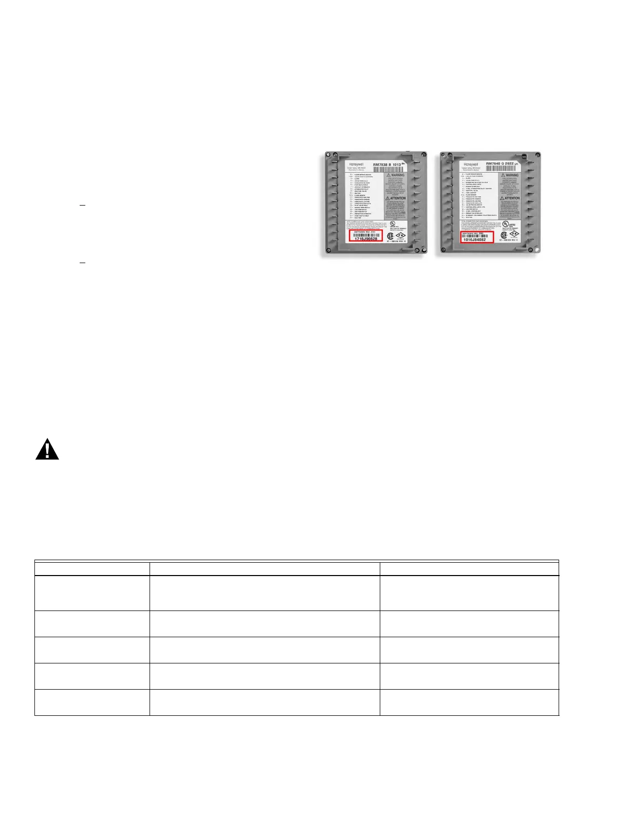
See Fig. 2 for Software Revision Level number location on
the label (located on the rear of the relay module).
Any relay module in the new 2000 series will only be able
to be installed on subbase Q7800A2005/U,
Q7800B2003/U and will not be backward compatible with
any Q7800A1003/U and Q7800A1005/U subbases
already installed in the field.
Fig. 2. Software revision location.
IMPORTANT
Make sure to check the relay model number and
the software revision level on the relay.
• If you attempt to place a 2000 series relay on a non-
compatible 1000 series subbase, you will receive an
error code of 101. This indicates that you must a)
change out the subbase to a Q7800A2003/U or
Q7800A2005/U or b) choose a compatible 1000 series
relay module.
Wiring Subbase
Electrical Shock Hazard.
Can cause serious personal injury, death or
equipment damage.
Disconnect the power supply before beginning
installation. More than one power supply
disconnect may be required.
1. Refer to Fig. 4 for proper subbase wiring.
2. For proper remote wiring of the KDM, refer to the
KDM Specifications (65-0288), Data ControlBus
Module™ (65-0091) or Extension Cable Assembly
(65-0131).
3. Make sure all wiring complies with all applicable
electrical codes, ordinances and regulations. Wiring,
where required, must comply with NEC, Class 1
(Line Voltage) wiring.
4. See Table 1 for recommended wire size and type.
Table 1. Recommended Wire Sizes and Part Numbers.
The KDM or Data ControlBus Module™ (for remote
mounting or communications) must be wired in a daisy
chain configuration,
1(a)-1(a), 2(b)-2(b), 3(c)-3(c). The order of interconnection
of all the devices listed above is not important. Be aware
that modules on the closest and farthest end of the daisy
Application Recommended Wire Size Recommended Part Numbers
Line voltage terminals
14, 16 or 18 AWG (0.75, 1.5 or 2.5 mm
2
) copper
conductor, 600 volt insulation, moisture-resistant
wire.
TTW60C, THW75C, THHN90C.
KDM
22 AWG (0.34 mm
2
) two-wire twisted pair with
ground, or five-wire.
Belden 8723 shielded cable or
equivalent.
Data ControlBus
Module™
22 AWG (0.34 mm
2
) two-wire twisted pair with
ground, or five-wire.
Belden 8723 shielded cable or
equivalent.
Remote Reset Module
22 AWG (0.34 mm
2
) two-wire twisted pair, insulated
for low voltage.
—
13 Vdc full wave rectified
transformer power input.
18 AWG (0.75 mm
2
) wire insulated for voltages and
temperatures for given application.
TTW60C, THW75C, THHN90C.