RM7838B, RM7838C 7800 SERIES RELAY MODULES
25 32-00211—01
APPENDIX A
Valve Proving Test
The Valve Proving System feature offers a systematic
way of testing the valve seat integrity to assure the valves
are indeed in the closed position when the system is off-
line, in STANDBY.
Explosion Hazard.
Can cause severe injury, death or property
damage.
Leaking gas valves can result in fire or explosion.
The Valve Proving System is designed to detect
such leaks. A valve proving test time that is too
short may allow unacceptable leaks to go
undetected. Use the procedure in Appendix A to
select sufficient valve test times to detect any
unacceptable leak.
The following steps are to determine the test time for the
relay module to verify the valve seats are not leaking at a
rate of greater than/equal to 0.1% of the burner capacity.
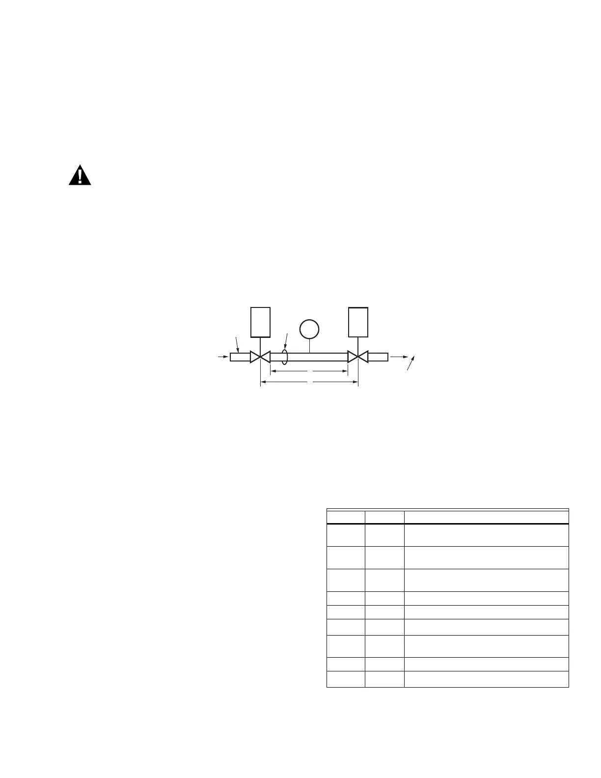
Fig. 28 shows a typical valve train. The legend identifies
information that will be used to fill out the worksheet that
appears at the end of this appendix.
1. Identify items of your system and fill in the “Informa-
tion” portion of the worksheet.
2. Go to the Lookup Tables noted (13, 14 or 15) to get
the results for your system.
IMPORTANT
The tables show information on Honeywell Valves
only. Contact other valve manufacturers to obtain
data on their specific valves.
Fig. 28. Typical valve train layout.
3. Use appropriate Results column items to fill in the
Valve Train Volume Formula and the Calculation of
Valve Proving Test Time.
4. Round up the time to the nearest second.
5. The test time calculated is the time you will enter
into the VPS Setup.
Calculation of Valve Train Volume
X = V1 + V2 + (A X L/144)
Calculation of Valve Proving Test
Time
Test Time = 187,000 x (P x X)/C
Table 10. Valve Proving Test Time Symbols
and Descriptions.
NOTE: V1 is the outlet cavity of the upstream valve and
V2 is the inlet cavity of the downstream valve.
V1
V2
VP
SW.
M22778
L
X
INLET
OUTLET
P
C
D
LEGEND
V1 UPSTREAM VALVE
V2 DOWNSTREAM VALVE
D PIPE DIAMETER (IN INCHES.) USED TO DETERMINE A;
ARE FOUND IN TABLE III
L PIPE LENGTH (IN FEET)
P VALVE INLET PRESSURE (PSIG)
C BURNER MAX. FIRING (CFH)
X CALCULATED TEST VALVE TRAIN VOLUME
Symbol Unit Description
X
ft
3
Volume between the two valves to be
tested.
V
1
ft
3
Volume of upstream valve outlet
cavity.
V2
ft
3
Volume of downstream valve inlet
cavity.
L ft Length of pipe between valves.
D npt Pipe Size—used to define A
A
in.
2
Pipe Cross Section Area (from Table III)
Test
Time
Second
s
Minimum VPS test period.
P psi Gas inlet pressure to upstream valve.
C
ft
3
/hr
Burner Capacity.
 Loading...