RM7838B, RM7838C 7800 SERIES RELAY MODULES
9 32-00211—01
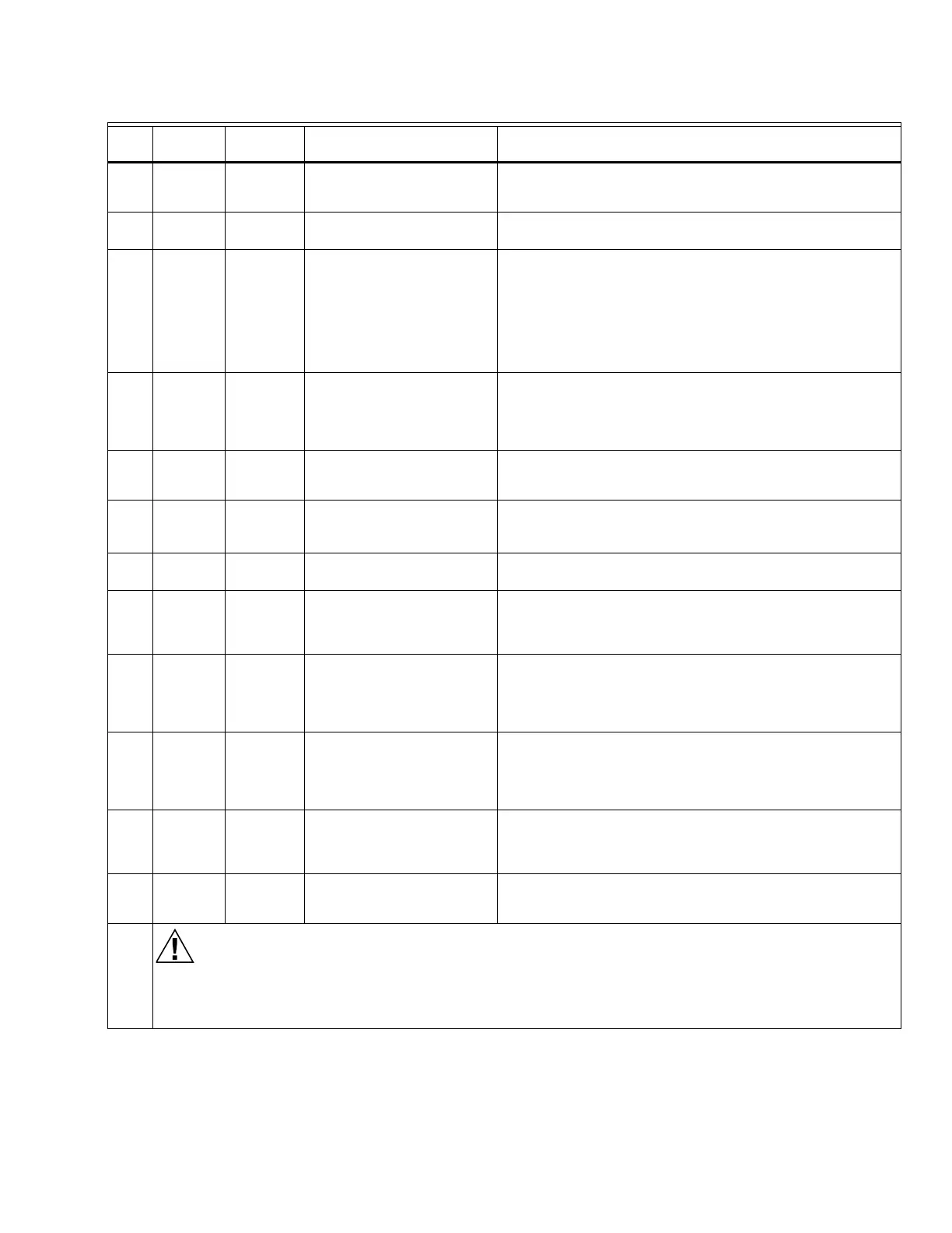
4 None 6-L2 Push and hold Stop Switch.
No voltage present at
terminal 6.
Stop Switch.
5 4-3 None Alarm (if used) turns on. 1. Alarm.
2. Alarm Silencing Switch.
6 4-5 7-L2 Close burner control.
Recirculating/exhaust
blower fan starts, then line
voltage is present at
terminal 6.
1. Combustion air fan starts.
2. Line voltage at terminal 7
within 10 seconds.
1. Combustion air fan circuit:
a. Manual switch on air fan motor.
b. Air fan power supply, overload protection, and starter.
2. Combustion Blower Air Flow Switch.
3. Alarm Silencing Switch.
4. Recirculating Air Flow Switch.
7 4-8 None Automatic pilot valve opens.
First stage valve
(DSI application only).
Ignition spark (if ignition
transformer connected).
1. Listen for click or feel head of valve for activation.
2. Watch for spark or listen for buzz:
a. Ignition electrodes are clean.
b. Ignition transformer is okay.
8 4-9 None Automatic main fuel valves
open. (DSI checks optional
second state fuel valve.)
Listen for and observe operation of the main fuel valve(s)
and actuator(s).
9 4-10 None Ignition spark (if ignition
transformer connected to
terminal 10.
1. Watch for spark or listen for buzz:
a. Ignition electrodes are clean.
b. Ignition transformer is okay.
10 4-17 None Line voltage at terminal 17. 1. Listen for click or feel valve head for actuation of main
valve # 2.
11 12-13 18-L2 Firing rate motor drives
open; zero volts at terminal
18 after motor leaves Low
Fire position.
1. Low Fire Start Switch.
2. Firing rate motor and transformer.
12 12-13 19-L2 Firing rate motor reaches
High Purge Rate position;
120 Vac at terminal 19
when High Purge Rate
Switch closes.
1. High Purge Rate Switch.
2. Firing rate motor and transformer.
13 13-14 19-L2 Firing rate motor leaves
High Purge Rate Position;
zero Vac at terminal 19
when High Purge Rate
Switch opens.
1. High Purge Rate Switch.
2. Firing rate motor and transformer.
14 13-14 18-L2 Firing rate motor drives to
Low Purge Rate position;
120 Vac at terminal 18
when switch closes.
1. Low Purge Rate Switch.
2. Firing rate motor and transformer.
15 13-15 None Adjust firing rate control
and watch tracking action of
the firing rate motor.
1. Firing rate control.
2. Firing rate motor and transformer.
Final
Electrical Hazard.
Can cause equipment damage.
After completing these tests, open the Master Switch and remove all test jumpers from the subbase terminals.
Also remove bypass jumpers from the low fuel pressure limits if used.
Table 3. Static Checkout. (Continued)
Test
No.
Test
Jumpers Voltmeter Normal Operation If Operation is Abnormal, Check These Items
 Loading...