RM7840E,G,L,M
ASSEMBLY
17 65-0087—2
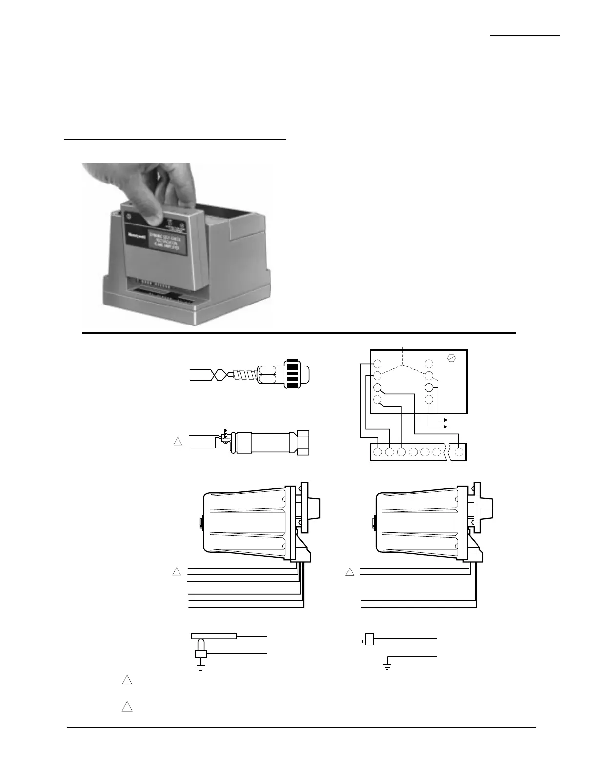
Fig. 16—Flame
detector wiring.
M1969
1
FLAME DETECTOR LEADS ARE COLOR CODED. THE BLUE LEAD MUST BE CONNECTED TO THE F TERMINAL AND THE WHITE
MUST BE CONNECTED TO THE G TERMINAL. THE UV SENSING TUBE IS POLARITY SENSITIVE. REVERSING THE LEADS EVEN
MOMENTARILY, CAN DAMAGE OR DESTROY THE UV TUBE.
FLAME DETECTOR LEADS ARE COLOR CODED. THE BLUE LEAD MUST BE CONNECTED TO THE F TERMINAL AND THE YELLOW
MUST BE CONNECTED TO THE G TERMINAL. THE UV SENSING TUBE IS POLARITY SENSITIVE. REVERSING THE LEADS EVEN
MOMENTARILY, CAN DAMAGE OR DESTROY THE UV TUBE.
2
BLUE
YELLOW
WHITE
WHITE
BLACK
BLACK
F
G
22
L2
L1
L2
BLUE
WHITE
F
G
WHITE
BROWN
F
G
INFRARED (C7015)
ULTRAVIOLET (C7027/C7035/C7044)
SOLID STATE SELF-CHECKING
ULTRAVIOLET (C7012E,F)
BLUE
YELLOW
BLACK
BLACK
F
G
L1
L2
SOLID STATE
ULTRAVIOLET (C7012A,C)
1
2
2
F G
4
5
3
L2
C7076A,D ULTRAVIOLET DETECTOR
5
22
6
SHUTTER
G
SHUTTER
F
1
8
2
7
7800 SERIES
L1
L2
3a
3b
REMOTE
SENSOR
2b
2a
EARTH
GROUND
C7076A
OR
C7076D
TERMINAL
BLOCK
L2 (COMMON)
L1 (HOT)
G
F
X
X
FLAME ROD
G
F
X
X
PHOTOCELL
the keyed receptacle on the RM7840. Verify the amplifier
nameplate faces away from the Relay Module, see Fig. 15.
3. Push in the amplifier until the circuit board is fully
inserted into the receptacle and then push the amplifier
toward the RM7840 retaining clasp.
4. Verify the amplifier is firmly in place.
5. Perform all required checkout tests.
INSTALLING FLAME DETECTOR
NOTE: Table 2 lists the flame detection systems available for
use with the RM7840. Make sure the correct combination
of amplifier and flame detector(s) is used.
Proper flame detector installation is the basis of a safe and
reliable flame safeguard installation. Refer to the Instructions
packed with the flame detector and the equipment manufac-
turer instructions, see Fig. 16.
Keep the flame signal leadwires as short as possible from
the flame detector to the wiring subbase. Capacitance in-
creases with leadwire length, reducing the signal strength.
The maximum permissible leadwire length depends on the
type of flame detector, leadwire and conduit. The ultimate
limiting factor in the flame detector leadwire is the flame
signal, see Table 6.
INSTALLING PLUG-IN FLAME SIGNAL
AMPLIFIER
1. Disconnect the power supply before beginning instal-
lation to prevent electrical shock and equipment damage.
More than one disconnect may be involved.
2. Align the amplifier circuit board edge connector with
Fig. 15—Flame signal amplifier mounting.
 Loading...

