sequence in PREPURGE with the firing rate motor in the
Low Fire position.
4. In PFEP, the Run/Test Switch, when placed in the
TEST position, will stop the timer during the first eight
seconds when a ten second PFEP is selected, or during the
first three seconds when a four second PFEP is selected,
allows for pilot-turn-down test and other burner adjustments.
This activates a fifteen second flameout timer that permits
pilot flame adjustment without nuisance safety shutdowns.
The Run/Test Switch is ignored during PFEP for the
RM7840E,L if terminals 8 and 9 or 9 and 21 are jumpered.
5. During RUN, the Run/Test Switch, when placed in the
TEST position, drives the firing rate motor to the Low Fire
position.
NOTE: When the RM7840 is switched to the TEST mode, it
stops and holds at the next Run/Test Switch point in the
operating sequence. Make sure that the RUN/TEST
SWITCH is in the RUN position before leaving the
installation.
WARNING
Do not use the Run/Test Switch during the Pilot
Flame Establishing Period for the RM7840G,M
when using direct spark ignition.
SELECTABLE SITE-CONFIGURABLE JUMPERS
The RM7840 has three site-configurable jumper options,
see Fig. 22 and Table 3. The site-configurable jumpers should
be clipped with side cutters and the resistors removed from
the Relay Module.
RM7840E,G,L,M
OPERATION
21 65-0087—2
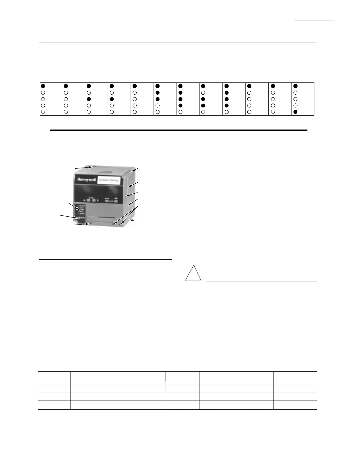
Fig. 20—LED sequence status display information.
Fig. 21—Relay Module and sequence status
LEDs (Fig. 20).
!
RUN/TEST SWITCH FUNCTIONS
The Run/Test Switch is located on the top side of the
RM7840, see Fig. 21. The Run/Test Switch allows the burner
sequence to be altered as follows:
1. In Prepurge Drive To High Fire position, the Run/Test
Switch when placed in the TEST position, holds in
PREPURGE with the firing rate motor in the High Fire
position.
2. In the measured PREPURGE sequence, the Run/Test
Switch, when placed in the TEST position, causes the
PREPURGE timing to stop. The firing rate motor is in the
High Fire position.
3. In Prepurge Drive to Low Fire position, the Run/Test
Switch, when placed in the TEST position, holds the burner
TABLE 3—SITE CONFIGURABLE JUMPER OPTIONS.
Jumper
Number Description Intact Clipped RM7840 Type
JR1 Pilot Flame Establishing Period (PFEP) 10 seconds 4 seconds ALL
JR2 Pilot Valve
b
(MFEP) Intermittent 15 or 30 seconds Interrupted
a
RM7840G
JR3 Start-up Interlock (ILK) Check Disable Enable ALL
a
A 30 second MFEP can be accomplished by adding a jumper wire between terminals 19 and 5.
b
Pilot Valve/First Stage Oil Valve (Valv/Start) Terminal 21.
BURNER SEQUENCE:
INITIATE
STANDBY
STANDBY
HOLD: F/G
(FLAME
DETECTED)
POWER
PILOT
FLAME
MAIN
POWER
PURGE
PILOT
FLAME
MAIN
PILOT
IGNITION
PURGE
HOLD: F/G
(FLAME
DETECTED)
ALARM
POWER
FLAME
MAIN
PILOT
ALARMALARM
POWER
FLAME
MAIN
PILOT
ALARM
POWER
FLAME
MAIN
PILOT
ALARM
POWER
FLAME
MAIN
PILOT
ALARM
POWER
FLAME
MAIN
PILOT
ALARM
POWER
FLAME
MAIN
PILOT
ALARM
POWER
FLAME
MAIN
PILOT
ALARM
POWER
FLAME
MAIN
PILOT
ALARM
RESET/
ALARM
TEST
RUN (WITH
INTERRUP-
TED PILOT)
RUN WITH
(INTERMIT-
TENT PILOT)
MAIN
IGNITION
M3359
POWER
FLAME
MAIN
PILOT
ALARM
POWER
FLAME
MAIN
PILOT
ALARM
POSTPURGE
STANDBY
NOTE: SEE TABLE 6 FOR FURTHER DETAILS OF HOLD CONDITIONS.
CAPTIVE
MOUNTING
SCREW
PLUG-IN PURGE
CARD
DUST COVER
RELAY MODULE
FLAME CURRENT
TEST JACKS
FLAME AMPLIFIER
RUN/TEST SWITCH
SEQUENCE
STATUS LEDs
RESET PUSH
BUTTON
FLAME
SIMULATOR INPUT
M7778
 Loading...

