RM7840E,G,L,M
CHECKOUT
PRELIMINARY INSPECTION
Perform the following inspections to avoid common
problems. Make certain that:
1. Wiring connections are correct and all terminal screws
are tight.
2. Flame detector(s) is clean, installed and positioned
properly. Consult the applicable Instructions.
3. Correct combination of amplifier and flame detector(s)
is used. See Table 2 in the Specifications.
4. Plug-in amplifier and purge card are securely in place.
5. Burner is completely installed and ready to fire; con-
sult equipment manufacturer instructions. Fuel lines are
purged of air.
6. Combustion chamber and flues are clear of fuel and
fuel vapor.
7. Power is connected to the system disconnect switch
(master switch).
8. Lockout is reset (push in reset button), only if the
RM7840 is powered, see Fig. 1 or 2.
9. Run/Test Switch is in RUN position.
10. System is in the STANDBY condition. POWER LED
is energized.
11. All limits and interlocks are reset.
FLAME SIGNAL MEASUREMENT (Table 5 and
Fig. 23)
CAUTION
If an RM7840 is replaced with a lower functioning
7800 SERIES Relay Module, the burner will not
sequence unless wiring changes are made.
IMPORTANT:
1. If the system fails to perform properly, refer to Trouble-
shooting section and 7800 SERIES System Annuncia-
tion and Troubleshooting, form 65-0118.
2. Repeat ALL required Checkout tests after all adjust-
ments are made. ALL tests must be satisfied with the
flame detector(s) in its FINAL position.
EQUIPMENT RECOMMENDED
Volt-ohmmeter (20 kohm/volt minimum sensitivity) with:
• 0-300 Vac capability.
• 0-6000 ohm capability.
• 0-10 Vdc capability.
CHECKOUT SUMMARY
• Preliminary inspection—all installations.
• Flame signal measurement—all installations.
• Initial lightoff check for proved pilot—all installations
using a pilot.
• Initial lightoff check for direct spark ignition of oil—
all burners using DSI.
• Pilot turndown test—all installations using a pilot.
• Hot refractory saturation test—all installations using
Infrared (lead sulfide) Flame Detectors.
• Hot refractory hold-in test—all installations.
• Ignition interference test—all installations using flame
rods.
• Ignition spark pickup—all installations using Ultra-
violet Flame Detectors.
• Response to other ultraviolet sources—all installa-
tions using Ultraviolet Flame Detectors.
• Flame signal with hot combustion chamber—all in-
stallations.
• Safety shutdown tests—all installations.
See Figs. 1 and 2 for location of component parts and see
Figs. 7, 8, 9, and 10 or Q7800 Specifications for terminal
locations.
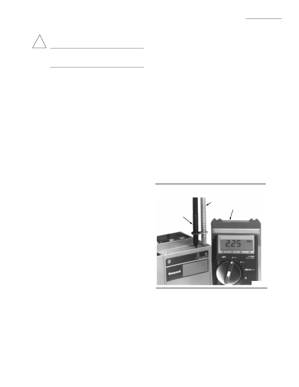
Fig. 23—Flame signal measurement.
25 65-0087—2
!
NEGATIVE (-)
METER LEAD
POSITIVE (+)
METER LEAD
20K OHM/
VOLT METER
M7554
 Loading...

