EasyManuals Logo

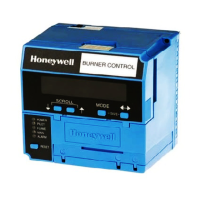
Honeywell RM7840L User Manual

Honeywell RM7840L
36 pages
To Next Page IconTo Next Page
To Previous Page IconTo Previous Page
Page #5 background imageLoading...
Page #5 background image
1 [32]
1
4
1
[45]
3
4
[21]
13
16
1 [35]
3
8
1 [33]
5
16
5
16
[8]1 [32]
1
4
2
[51]
C7013A C7014A
M1847
RM7840E,G,L,M
SPECIFICATIONS
5 65-0087—2
MOUNTING FLANGE
7 [183]
7
32
3
[87]
7
16
3
[95]
3
4
5
[130]
1
8
5 [133]
1
4
1/2–14 NPSM
LEADWIRES
FACEPLATE
3/4–14 NPT OR
1–11-1/2 NPT
M1962
THREADED
MOUNTING
HOLES (2)–
10-32 UNF
[13]
1
2
1 [25]
FLAME ROD
[18]
11
16
3
8
[10]
[2]
3
32
[20]
25
32
[20]
25
32
[14]
17
32
TARGET
2 [62]
25
32
1
[27]
1
16
1
[36]
13
32
1
[42]
21
32
3
[79]
1
8
CERAMIC
INSULATORS
IGNITION
ELECTRODE
(Q179C ONLY)
BRACKET
M1983
Q179
C7012A,C,E,F
Fig. 3—Rectification detectors.
POWER
PILOT
FLAME
MAIN
ALARM
RESET
5
[127]
5 [127]
M5004A
6 [155]
3
32
BURNER CONTROL
REMOVE ONLY FOR TERMINAL TEST ACCESS.
1
1
Fig. 2—Mounting dimensions of RM7840 Relay Module and Q7800B Subbase, in inches [millimeters].

Other manuals for Honeywell RM7840L

Questions and Answers:

Question and Answer IconNeed help?

Do you have a question about the Honeywell RM7840L and is the answer not in the manual?

Honeywell RM7840L Specifications

General IconGeneral
BrandHoneywell
ModelRM7840L
CategoryControl Unit
LanguageEnglish

Related product manuals