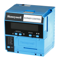
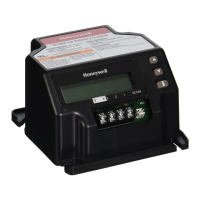
RM7890A,B,C/EC7890A,B 7800 SERIES RELAY MODULES
5 66-1089—11
Table 4. Combinations for Terminals 8, 9, and 10.
Final Wiring Check
1. Check the power supply circuit. The voltage and
frequency tolerance must match those of the
RM/EC7890. A separate power supply circuit can be
required for the RM/EC7890. Add the required
disconnect means and overload protection.
2. Check all wiring circuits and complete the Static
Checkout in Table 7 before installing the RM/EC7890 on
the subbase.
3. Install the relay module.
4. Restore the panel power.
STATIC CHECKOUT
After checking all wiring, perform this checkout before
installing the RM/EC7890 on the subbase. These tests verify
the Q7800 Wiring Subbase is wired correctly, and the external
controllers, limits, interlocks, actuators, valves, transformers,
motors and other devices are operating properly.
Explosion Hazard.
Can cause serious injury, death or equipment
damage.
1. Close all manual fuel shutoff valve(s) before starting
these tests.
2. Use extreme care while testing the system. Line
voltage is present on most terminal connections
when power is on.
3. Open the master switch before installing or
removing a jumper on the subbase.
4. Before continuing to the next test, be sure to
remove test jumper(s) used in the previous test.
5. Replace all limits and interlocks that are not
operating properly. Do not bypass limits and
interlocks.
Equipment Damage Hazard.
Can cause equipment damage or equipment
failure.
Do not perform a dielectric test with the RM/EC7890
installed. Internal surge protectors break down and
conduct a current, causing the RM/EC7890 to fail the
dielectric test or possibly destroy the internal lightning
and high current protection.
Equipment Recommended
1. Voltmeter (1M ohm/volt minimum sensitivity) set on the
0 to 300 Vac scale.
2. Two jumper wires, No. 14 wire, insulated, 12 in.
(304.8 mm) long with insulated alligator clips at both
ends. Note that an ammeter can be used in place of a
jumper to confirm current draw of loads. (ignition, pilot
valve and main valve).
General Instructions
1. Perform all applicable tests listed in the Static Checkout,
Table 6, in the order listed.
2. Make sure all manual fuel shutoff valves are closed.
3. For each test, open the master switch and install the
jumper wires between the subbase wiring terminals
listed in the Test Jumpers column.
4. Close the master switch before observing the operation.
5. Read the voltage between the subbase wiring terminals
listed in the Voltmeter column.
6. If there is no voltage or the operation is abnormal, check
the circuits and external devices as described in the last
column.
7. Check all wiring for proper connections, tight terminal
screws, and appropriate wire and wiring techniques.
8. Replace all damaged or incorrectly sized wires.
9. Replace faulty controllers, limits, interlocks, actuators,
valves, transformers, motors and other devices, as
required.
10. Make sure normal operation is obtained for each
required test before continuing the checkout.
11. After completing each test, be sure to remove the test
jumper(s).
Pilot Fuel 8 Main 9 Ignition 10
C F No Load
B F No Load
FFA
F No Load A
DFA
DDA
D No Load A
AB C D F
4.5A ignition 50 VA Pilot Duty plus
4.5A ignition.
180 VA ignition plus motor
valves with: 660 VA inrush,
360 VA open, 250 VA hold.
2A Pilot Duty. 65 VA Pilot Duty plus motor
valves with: 3850 VA inrush,
700 VA Open, 250 VA hold.
 Loading...