RTH7400/RTH7500 Series
23 69-2487EF—01
SETUP WIRING ASSISTANCE TROUBLESHOOTING
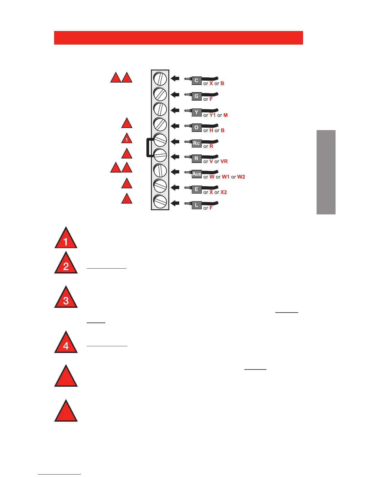
Leave metal jumper in place, connecting R & Rc
terminals.
If your old thermostat had both V and VR wires,
stop now and contact a qualified contractor for
help.
If your old thermostat had separate O and B
wires, attach the B wire to the C terminal. If
another wire is attached to the C terminal, stop
now and contact a qualified contractor for help.
If your old thermostat had Y1, W1 and W2 wires,
stop now and contact a qualified contractor for
help.
If L terminal is used, C terminal wire must be
connected (contact a contractor if there is no C
wire).
If E and Aux terminals do not each have a wire
connected, use a small piece of wire to connect
them to each other.
Wiring—heat pump
Alternate wiring (for heat pumps only)
Wiring complete, return to Step 7.
 Loading...