S05, S10, S20 SERIES SPRING RETURN DIRECT COUPLED ACTUATORS
3 62-0188—09
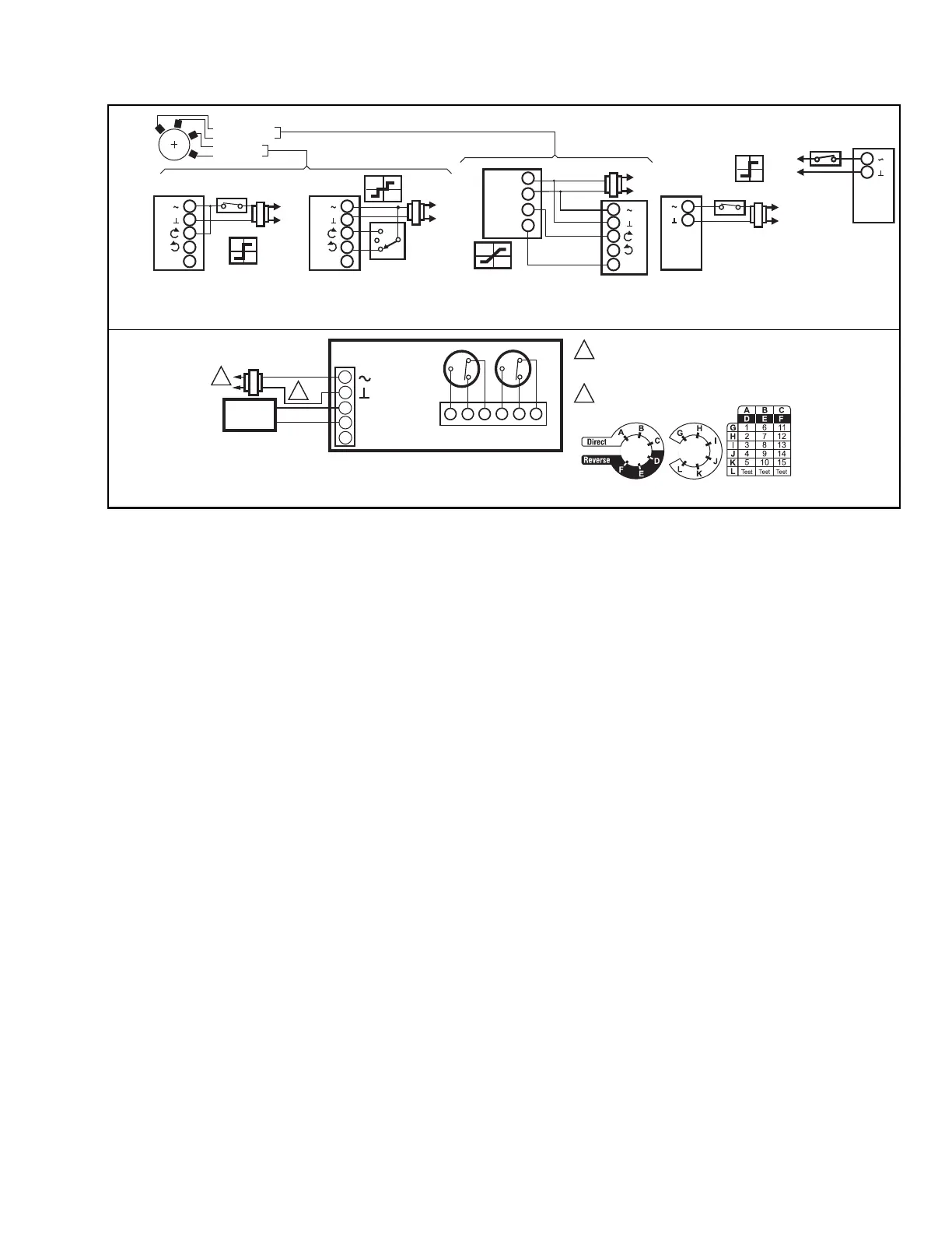
For additional installation details go to customer.honeywell.com and search for Literature Number 63-2607.
L1
L2
L1
M19570D
L2
L1
L2
MS7XXX
Modulating, ...
Modulating, ...
Floating, ...
Floating, ...
2
1
L2
L1
MS81XX
L1
L2
MS4XXX
1
2
F
5
4
3
1
2
F
5
4
3
1
2
F
5
4
3
1
2
MS7XXX
MS7XXX
24 VAC
24 VAC
100-250 VAC
24 VAC
24 VAC
COM
+
HOT
F
S-BUS
LINE VOLTAGE POWER SUPPLY. PROVIDE
DISCONNECT MEANS AND OVERLOAD
PROTECTION AS REQUIRED.
24 VDC SUPPLY ACCEPTABLE.
M34297
1
2
1
2
S-BUS
24 VAC
ACTUATOR
1
2
3
4
5
S-BUS
S-BUS
V
S1 S2
S3
S4 S5
S6
85º
85º
Intended to be installed with a flexible metal conduit.
C1
The internal auxiliary switches must be connected to the same power source, the auxiliary switches shall be connected to the
same pole of the same supply circuit, connected in a same polarity manner.
C
 Loading...


