65-0315—02 36
“On” status is indicated by a green LED and “Off” status is
indicated by a gray LED.
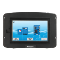
Analog I/O data is displayed as bar charts depicting the I/O
level (see Fig. 78). Analog I/O that is not enabled for the
installation displays a blank I/O level. To see all analog I/O,
use the horizontal scroll bar to move the view left and right.
Fig. 78. Diagnostics analog I/O page.
INSTALLER CHECKOUT
Diagnostics Tests
Pressing the Diagnostics Test button launches the diagnostic
tests. The first test displayed on the right side of the screen is
the last selected test shown, as seen in Fig. 79.
This screen enables the user to perform the following tests:
Modulation Test: enables the user to verify that the burner is
firing at the correct rate. (See Fig. 79.)
Pilot Test: enables the user to verify that the pilot valve is
functioning properly. The user can also perform burner
adjustments for the pilot flame. (See Fig. 80.)
Pump Test: enables the user to verify that the correct pump is
on or off. The Start Test button will test all pumps; pressing an
individual pump tests that pump only. (See Fig. 81.)
Burner Switch: this button turns the burner on or off.
Start Test: runs the test for 5 minutes.
Fig. 79. Modulation test.
Table 56. Control Digital I/O Data.
Data Comment
Pump A On/Off
Pump B On/Off
Pump C On/Off
Blower/HSI On/Off
Pilot valve On/Off
Main valve On/Off
Load Control Input On/Off
STAT On/Off
Pre-ignition interlock On/Off
Interlock On/Off
External ignition On/Off
Alarm On/Off
Pilot test hold On/Off
Time Of Day On/Off
Safety relay On/Off
Low Gas On/Off
High Gas On/Off
Annunciator 3 On/Off
Annunciator 4 On/Off
PM On/Off
Annunciator 5 On/Off
Annunciator 6 On/Off
Annunciator 7 On/Off
Annunciator 8 On/Off
PM Lead/Lag On/Off
Table 57. Control Analog I/O Data.
Data Comment
Outlet
Inlet If enabled
Firing rate % or RPM
Flame signal V
Fan speed RPM (if applicable). Should
match with firing rate.
Domestic Hot Water If enabled
Stack If enabled
Outdoor If enabled
Header If enabled

 Loading...