Do you have a question about the Honeywell SILENT KNIGHT 5496 and is the answer not in the manual?
| SLC Loops | 1 |
|---|---|
| Battery Charging Current | 1.5A |
| Operating Temperature | 32°F to 120°F (0°C to 49°C) |
| Relative Humidity | 10% to 93% non-condensing |
| Type | Fire Alarm Control Panel |
| Zones | Not applicable |
| Number of Zones | Not applicable |
| Power Supply | 120 VAC, 60 Hz |
| Annunciators | Not applicable |
| Communication | Not applicable |
| Communication Protocol | Not applicable |
Discusses reasons why smoke detectors may fail to sense fires and their inherent sensing limitations.
Explains limitations of heat detectors and their purpose for property protection.
Mandates installing smoke detectors in the same room as the control panel and communication rooms.
Covers limitations of audible warning devices, voice messaging, and strobes, including user response.
Emphasizes disconnecting all power sources before servicing control units and associated equipment.
Outlines mandatory re-testing after software changes or system component modifications per NFPA 72.
Covers environmental operating ranges, wire adequacy, protection from transients and ESD.
Details FCC requirements for Class A devices regarding radio frequency energy emissions.
States compliance with Canadian limits for digital apparatus radio noise emissions.
Advises users to download the latest software for product features and functionality.
Instructs users on how to provide feedback for improving manuals and online help.
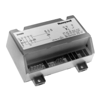
Introduces the 5496 Intelligent Power Module and its role in powering notification appliances and auxiliary circuits.
Lists general and specific agency requirements, including UL 864 editions and installation restrictions.
Provides contact details for technical support and sales for inquiries or assistance.
Lists the hardware components included with the 5496 module, including cabinet, keys, and resistors.
Details the recommended environmental operating ranges for temperature and humidity for optimal system performance.
Advises on precautions to prevent water damage to the cabinet, particularly from conduit entries.
Guides users on determining current draw and calculating standby battery requirements for the installation.
Displays maximum load capacities for different battery sizes over 24 and 60 hours of standby.
Offers a detailed worksheet to calculate the current draw of the system for battery sizing.
Details the 5496 circuit board layout, including terminals and DIP switches for module ID.
Provides a table with terminal descriptions, voltage, and current ratings for the 5496 connections.
Details earth fault resistance values for specific terminals to aid in fault detection.
Specifies power-limited wiring techniques and spacing requirements for safe installation.
Explains how to connect the 120 VAC power source to the AC terminals of the 5496.
Details how to connect 12V batteries in series to provide 24-volt backup power for the module.
Guides on connecting the 5496 to the FACP via SBUS and setting the module ID.
Explains how to use the DIP switch on the 5496 board to assign a unique module ID (1-31).
Introduces wiring for notification appliances and compatibility checks with compatible appliances.
Illustrates how to wire two 3-amp devices as Class A circuits using in/out wiring methods.
Details Class A supervised wiring for notification circuits, including loop-back and built-in EOL.
Explains Class B supervised wiring, requiring external EOL resistors for notification appliance circuits.
Describes wiring for releasing operations, emphasizing Class B wiring and NFPA 72 spacing rules.
Guides on configuring output circuits for door holder, constant, resettable, or sync power modes.
Details door holder, constant, resettable, and sounder sync power, including their operational characteristics.
Outlines the 36-month warranty period, conditions, and exclusions for manufactured products.
Disclaims further warranties, including fitness for purpose, and limits liability for personal injury or death.
Describes the procedure for submitting warranty claims, including required authorization and return process.