[7] FIELD WIRING; INSTALLATION GUIDELINES
All wiring must be installed in compliance with the National Electrical Code
and the local codes having jurisdiction. Proper wire gauges should be used.
The conductors used to connect smoke detectors to control panels and acces-
sory devices should be color-coded to prevent wiring mistakes. Improper con-
nections can prevent a system from responding properly in the event of a fire.
For signal wiring (the wiring between detectors or from detector to auxiliary
devices), it is usually recommended that single conductor wire be no smaller
than 18 gauge. The duct smoke detector terminals accommodate wire sizes up
to 12 gauge. Flexible conduit is recommended for the last foot of conduit; solid
conduit connections may be used if desired.
Duct smoke detectors and alarm system control panels have specifications for
Signaling Line Circuit (SLC) wiring. Consult the control panel manufacturer’s
specifications for wiring requirements before wiring the detector loop.
[7.1] WIRING INSTRUCTIONS
Disconnect power from the communication line before installing the SK-Duct
duct smoke detector.
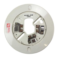
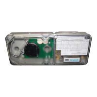
The SK-Duct detectors are designed for easy wiring. The housing provides a
terminal strip with clamping plates. Wiring connections are made by sliding
the bare end under the plate, and tightening the clamping plate screw. See
Figure 6 below for system wiring.
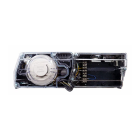
[7.2] SET THE ADDRESS
Set the desired address on the sensor head code wheel switches on the back
of the sensor head.
[8] VERIFICATION OF OPERATION
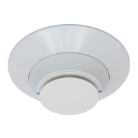
[8.1] INSTALL THE COVER
Install the covers making sure that the cover fits into the base groove. Tighten
the seven screws that are captured in the covers. Note that the cover must be
properly installed for proper operation of the sensor.
[8.2] POWER THE UNIT
Activate the communication line on terminals COM + and COM –.
[8.3] DETECTOR CHECK
Standby – If programmed by the system control panel, look for the presence of
the flashing LEDs through the transparent housing cover. The LED will flash
with each communication.
Trouble – If programmed by the system control panel and the detector LEDs
do not flash, then the detector lacks power (check wiring, missing or improp-
erly placed cover, panel programming, or power supply), the sensor head is
missing (replace), or the unit is defective (return for repair).
[8.4] DUCT SMOKE DETECTOR TEST & MAINTENANCE PROCEDURES
Test and maintain duct smoke detectors as recommended in NFPA 72. The
tests contained in this manual were devised to assist maintenance personnel
in verification of proper detector operation.
Before conducting these tests, notify the proper authorities that the smoke
detection system will be temporarily out of service. Disable the zone or system
under test to prevent unwanted alarms.
[8.4.1] TEST THE UNIT
1. M02-04-00 Magnet Test (not included) – This sensor can be functionally
tested with a test magnet. The test magnet electronically simulates smoke
in the sensing chamber, testing the sensor electronics and connections to
the control panel.
2. Remote Test Accessory – The use of a remote accessory for visible indica-
tion of power and alarm is recommended.
Verify system control panel alarm status and control panel execution of all
intended auxiliary functions (i.e. fan shutdown, damper control, etc.).
Two LEDs on the sensor are controlled by the panel to indicate sensor
status. Coded signals, transmitted from the panel, can cause the LEDs
to blink, latch on, or latch off. Refer to the control panel technical docu-
mentation for sensor LED operation and expected delay to alarm.
[8.4.2] THE DETECTOR MUST BE RESET BY THE SYSTEM CONTROL PANEL
[8.4.3] SMOKE ENTRY TEST USING AEROSOL SMOKE
This test is intended for low-flow systems (100-500 FPM). If the air speed is
greater than 500 FPM, use a conventional manometer to measure differential
pressure between the sampling tubes, as described under Measurement Tests
on Page 3.
Drill a
1
⁄4-inch hole 3 feet upstream from the duct smoke detector. With the air
handler on, measure the air velocity with an anemometer. Air speed must be
at least 100 FPM. Spray aerosol smoke* into the duct through the
1
⁄4-inch hole
for five seconds. Wait two minutes for the duct smoke detector to alarm. If the
duct smoke detector alarms, air is flowing through the detector. Remove the
duct smoke detector cover and blow out the residual aerosol smoke from the
chamber and reset the duct smoke detector at the panel. Use duct tape to seal
the aerosol smoke entry hole. Remember to replace the cover after the test or
the detector will not function properly.
*Aerosol smoke can be purchased from Home Safeguard Industries at
homesafeguard.com, model 25S Smoke Detector Tester, and Chekkit Smoke
Detector Tester model CHEK02 and CHEK06 available from SDi. When used
properly, the canned smoke agent will cause the smoke detector to go into
alarm. Refer to the manufacturer’s published instructions for proper use of the
canned smoke agent.
Canned aerosol simulated smoke (canned smoke agent) formulas will vary by
manufacturer. Misuse or overuse to these products may have long term adverse
effects on the smoke detector. Consult the canned smoke agent manufacturer’s
published instructions for any further warnings or caution statements.
[9] DETECTOR CLEANING PROCEDURES
Notify the proper authorities that the smoke detector system is undergoing
maintenance, and that the system will temporarily be out of service. Disable
the zone or system undergoing maintenance to prevent unwanted alarms and
possible dispatch of the fire department.
[9.1] DETECTOR SENSOR
1. Remove the sensor to be cleaned from the system.
2. Remove the sensor cover by pressing firmly on each of the four removal
tabs that hold the cover in place.
3. Vacuum the screen carefully without removing it. If further cleaning is re-
quired continue with Step 4, otherwise skip to Step 7.
4. Remove the chamber cover/screen assembly by pulling it straight out.
5. Use a vacuum cleaner or compressed air to remove dust and debris from
the sensing chamber.
6. Reinstall the chamber cover/screen assembly by sliding the edge over the
sensing chamber. Turn until it is firmly in place.
7. Replace the cover using the LEDs to align the cover and then gently pushing
it until it locks into place.
8. Reinstall the detector.
FIGURE 6. SYSTEM WIRING DIAGRAM FOR SK-DUCT:
HO572-00
COMM.
LINE (+)
ANEL
1ST
DETECTOR
IN LOOP
2ND
DETECTOR
IN LOOP
COMM.
LINE (–)
COMM.
LINE
HO112-01
FIGURE 7. ROTARY ADDRESS SWITCHES
4 I56-3432-006
04-12
 Loading...