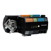
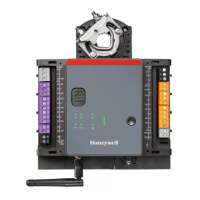
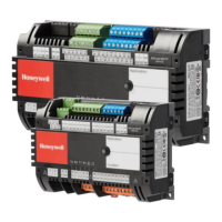
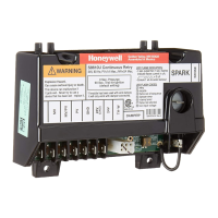
SPYDER® LON PROGRAMMABLE, VAV/UNITARY CONTROLLERS
13 63-2685—03
Table 6. Description of wiring terminal connections for
PUL6438S, PVL6436AS, and PVL6438NS.
Table 7. Description of wiring terminal connections for
PUL1012S, PUL4024S, PVL0000AS, PVL4022AS, and
PVL4024NS.
IMPORTANT
If the controller is not connected to a good earth
ground, the controller's internal transient protection
circuitry is compromised and the function of protect-
ing the controller from noise and power line spikes
cannot be fulfilled. This could result in a damaged cir-
cuit board and require replacement of the controller.
Refer to installation diagrams for specific wiring.
Terminal Label Connection
INPUT POWER & GROUND
1 24 Vac 24 Vac Power
2 24 Vac COM 24 Vac Power
3 EGND Earth Ground
4 SHLD Shield
5SBUS 1 Sylk
6SBUS 2 Sylk
NETWORK CONNECTIONS
7NET-1 LONWORKS® communications
8NET-2 LONWORKS® communications
DIGITAL OUTPUTS
a
9DO-1 Digital Output
10 DO-2 Digital Output
11 COM Common
12 DO-3 Digital Output
13 DO-4 Digital Output
14 COM Common
15 DO-5 Digital Output
16 DO-6 Digital Output
17 COM Common
18 DO-7 Digital Output
19 DO-8 Digital Output
20 COM Common
ANALOG OUTPUTS
b
21 AO-1 Analog Output
22 COM Common
23 AO-2 Analog Output
24 AO-3 Analog Output
25 COM Common
DIGITAL INPUTS
c
26 DI-1 Digital Input
27 DI-2 Digital Input
28 COM Common
29 DI-3 Digital Input
30 DI-4 Digital Input
ATTACHED DEVICE(S) POWER
31 20 Vdc 20 Vdc Power
UNIVERSAL INPUTS
32 UI-1 Universal Input
33 COM Common
34 UI-2 Universal Input
35 UI-3 Universal Input
36 COM Common
37 UI-4 Universal Input
38 UI-5 Universal Input
39 COM Common
40 UI-6 Universal Input
a
For the PVL6436AS controller ONLY, terminals 18, 19, and 20 (DO7,
DO8, & COM) are not present. The actuator is internally hardwired to
these terminals.
b
Analog outputs may be configured as digital outputs and operate as fol-
lows:
– False (0%) produces 0 Vdc, (0 mA)
– True (100%) produces the maximum 11 Vdc (22 mA)
c
Digital inputs: Open circuit = False; Closed circuit = True
Terminals,
PUL4024S,
PVL4024NS
Terminals,
PVL4022AS
a
Terminals,
PUL1012S
Terminals,
PVL0000AS
a
Label Connection
INPUT POWER & GROUND
1 1 1 1 24 Vac 24 Vac Power
222224 Vac
COM
24 Vac Power
3 3 3 3 EGND Earth Ground
4 4 4 4 20 Vdc 20 Vdc Power
5 5 5 5 SBUS 1 Sylk
6 6 6 6 SBUS 2 Sylk
NETWORK CONNECTIONS
7 7 7 7 NET-1 LonWorks®
communications
8 8 8 8 NET-2 LonWorks®
communications
DIGITAL OUTPUTS
b
9 NA NA NA DO-3 Digital Output
10 NA NA NA COM Common
11 NA NA NA DO-4 Digital Output
12 NA NA NA COM Common
13 13 13 NA DO-1 Digital Output
14 14 14 NA DO-2 Digital Output
15 15 15 NA COM Common
ANALOG OUTPUTS
c
16 16 16 NA AO-1 Analog Output
17 17 17 NA COM Common
18 18 NA NA AO-2 Analog Output
UNIVERSAL INPUTS
19 19 19 NA UI-1* Universal Input
d
20 20 20 NA COM Common
21 21 NA NA UI-2 Universal Input
22 22 NA NA UI-3 Universal Input
23 23 NA NA COM Common
24 24 NA NA UI-4 Universal Input
a
For the PVL0000AS and PVL4022AS controllers, DO3 and DO4 are
internally hardwired to the actuator.
b
Digital inputs: Open circuit = False; Closed circuit = True
c
Analog outputs may be configured as digital outputs and operate as fol-
lows:
- False (0%) produces 0 Vdc, (0 mA)
- True (100%) produces the maximum 11 Vdc (22 mA)
b
Digital inputs: Open circuit = False; Closed circuit = True
d
UI-1* is a hybrid input. It can be configured as either a DI (fast digital
pulse meter) or a UI.

 Loading...
