Do you have a question about the Honeywell SmartValve SV9510 and is the answer not in the manual?
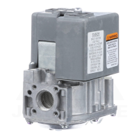
Defines the physical form factor of the control unit.
Details voltage, frequency, and output load ratings for the control.
Discusses appliance cycling rates and potential wear on controls.
Advises on protecting controls during cleaning to prevent damage.
Highlights the danger of moisture on controls and proper installation.
Instructions for attaching flanges to the control inlet or outlet.
Guidance on installing threaded bushings into the control ports.
Guidance on pipe thread depth, compound application, and connection procedures.
Verifies ground commonality between appliance chassis and AC line neutral.
Explains the function of the ignition system control switch settings.
Covers gas leak testing, checking gas input, and adjusting burner ignition.
Guidelines for determining maintenance frequency and system replacement.
Diagnosing issues using the LED indicator and associated flash codes.
Diagnosing issues when the LED indicator is not available or functioning.
Critical safety advice, especially regarding gas leaks and appliance operation.
Steps to follow if the appliance does not turn on when the thermostat is set.
Instructions for vacation shutdown and complete appliance shutdown.
The Honeywell SV9510/SV9520 SmartValve™ System Controls are integrated gas flow control and electronic direct main burner ignition sequencing units designed for a wide range of fan-assisted combustion, gas-fired appliances. These include furnaces, rooftop furnaces, boilers, unit heaters, infrared heaters, water heaters, and commercial cooking appliances. The system utilizes a 120V hot surface igniter to light the main burner flame, and it incorporates all necessary gas ignition safety functions by controlling gas flow, the ignition source, and a 120 Vac combustion air blower.
The SmartValve™ System Controls manage the complete ignition sequence of a gas appliance. This includes prepurge, postpurge, and a timed trial for ignition, with provisions for multiple ignition trials and an auto-reset from lockout. A diagnostic LED provides real-time system status, aiding in troubleshooting.
The control monitors the appliance airflow proving switch circuit and the limit string to ensure proper appliance operation. This comprehensive monitoring helps maintain safe and efficient performance. In typical forced warm air furnace applications, the control communicates directly with the ST9160 Electronic Fan Timer (EFT). It can also interface with the 208907 Terminal Board, offering compatibility with power-stealing thermostats, or directly with appropriate power supplies and a system thermostat for other appliance applications. When controlled directly by a thermostat, the control does not provide a postpurge function, as power is removed when the thermostat call for heat ends.
Line voltage polarity sensing models are available, which monitor the line voltage input connection to ensure correct polarity. If the line voltage polarity is incorrect, the LED diagnosis code will flash, and the control will not respond to a call for heat. These models also provide additional LED diagnostic codes to indicate when the control has entered a lockout state.
The SmartValve™ System Controls are designed for direct replacement, ensuring compatibility with existing systems. They come factory-set for either natural (and manufactured) gas or LP gas, with conversion kits available for switching between gas types for models with standard or slow-opening regulators. However, step-opening regulators (SV9510P/SV9520P) cannot be field-converted.
Installation involves mounting the control in the appliance vestibule on the gas manifold. Adapters (flanges or bushings) can be installed on the control's inlet and outlet. When installing flanges, it's crucial to ensure the O-ring is properly fitted and the screws are tightened to the specified torque for a gas-tight seal. For bushings, a moderate amount of good quality pipe compound (resistant to LP gas for LP installations) should be applied, leaving two end threads bare to prevent valve distortion.
Piping must comply with local codes and standards, using new, properly reamed pipe or tubing with smooth bends. A sediment trap must be installed in the supply line to prevent contamination. The control can be mounted from 0 to 90 degrees in any direction, including vertically, from the upright position of the ignition system control switch, with gas flow in the direction of the arrow on the bottom of the control.
Wiring must adhere to appliance manufacturer instructions and applicable electrical codes. A minimum 40 VA NEMA-rated system transformer is required. The appliance chassis must have a reliable connection to earth ground, and the 120 Vac hot supply lead must be correctly connected. A ground commonality check using a multimeter is recommended to ensure the voltage reading between the appliance chassis and the neutral side (L2) of the line voltage is less than ten volts.
The control features an ON/OFF switch. The OFF position prevents main gas flow, while ON permits gas flow through the control body at the appropriate time. Controls are typically shipped in the ON position. If the appliance operates with the switch in the OFF position, the system will respond as if the air proving switch is stuck in the no airflow position.
A gas leak test must be performed after installation, using a rich soap and water solution on all pipe connections. It's important not to spray the solution directly on the SmartValve™ housing to avoid damage. Gas input and burner ignition should be checked and adjusted according to appliance nameplate ratings and manufacturer instructions, using either a clocking gas meter or a manometer. Inlet pressure should be checked before adjusting the pressure regulator. For step-opening pressure regulators, burner lightoff at step pressure should be carefully checked to ensure smooth ignition without flashback.
Regular preventive maintenance is crucial, especially in commercial cooking, agricultural, and industrial applications where controls experience heavy cycling, exposure to moisture, dirt, chemicals, and heat. These conditions can lead to accelerated wear and potential control failure.
The maintenance program should include regular checkout of the control as outlined in the Startup and Checkout section, and the control system as described in the appliance manufacturer literature. Maintenance frequency depends on cycling frequency (monthly for appliances cycling 200,000 times annually), intermittent use (before shutdown and again before next use for seasonal appliances), the consequence of unexpected shutdown (more often if high cost), and environmental conditions (more often in dusty, wet, or corrosive environments).
The control should be replaced if it does not perform properly during checkout or troubleshooting, if it has operated for more than 200,000 cycles, or if it is wet or shows signs of having been wet. Disassembly or repair of the ignition system control is not recommended as it contains no replaceable components and attempted repair can cause damage or gas leakage.
Troubleshooting assistance is provided through the diagnostic LED indicator, which flashes specific codes to indicate system status or lockout reasons. For situations where appliance power or thermostat call for heat has cycled since a failure occurred, troubleshooting without LED indicator assistance involves checking power, gas supply, switch positions, and jumpering thermostat terminals to observe appliance operation.
Homeowners are advised to follow specific instructions in case of a gas smell, including turning off the gas supply, avoiding electrical switches, and evacuating the building to call the gas supplier or fire department. The ignition system control must be replaced if there is any physical damage, tampering, bent terminals, missing or broken parts, stripped threads, or evidence of heat exposure. For appliance startup issues, homeowners are instructed to reset the thermostat, disconnect power, move the ignition system control switch to OFF, wait five minutes, then move it to ON, replace the access panel, reconnect power, and set the thermostat. If the appliance still doesn't turn on, a qualified service technician should be contacted.
| Type | SmartValve |
|---|---|
| Model Number | SV9510 |
| Voltage | 24 Vac |
| Control Type | Electronic |
| Output Current | 0.5A |
| Ignition Type | Intermittent pilot |
| Gas Type | Natural gas |
| Frequency | 60 Hz |
| Humidity Range | 5 to 95% RH non-condensing |