SV9510/SV9520 SMARTVALVE™ SYSTEM CONTROLS
9 69-2014
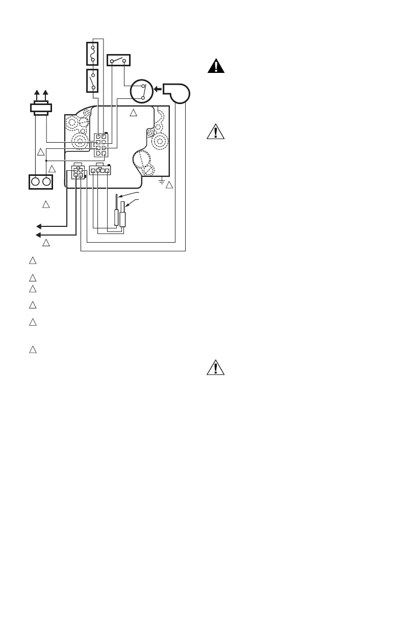
Fig. 10. SV9510/SV9520 typical wiring connections
direct to the system thermostat.
STARTUP AND CHECKOUT
Ignition System Control Switch Settings
Ignition system control switch settings are as follows:
OFF prevents main gas flow through the ignition
system control.
ON permits gas to flow through the control body. At the
appropriate time in the appliance operation, main gas
can flow to the main burner.
NOTE: Controls are shipped with the ignition system
control switch in the ON position. If the appliance
is operated with the ignition system control
switch in the OFF position, the system will
respond as if the air proving switch is stuck in the
no airflow position.
Turn on Main Burner
Follow the instructions provided by the appliance
manufacturer or turn up the thermostat to call for heat.
Perform Gas Leak Test
WARNING
Fire or Explosion Hazard.
Can cause property damage, severe injury or
death.
Check for gas leaks with soap and water solution
any time work is done on a gas system.
CAUTION
Equipment Damage Hazard.
Liquid can damage the SmartValve™ Control.
Do not spray soap and water solution on the
SmartValve™ housing. Do not use an excessive
amount of soap and water solution to perform the
gas leak test. These can damage the control.
Gas Leak Test
1. Paint pipe connections upstream of the ignition sys-
tem control with rich soap and water solution. Bub-
bles indicate a gas leak.
2. If a leak is detected, tighten the pipe connections.
3. Stand clear of the main burner while lighting to
prevent injury caused from hidden leaks that could
cause flashback in the appliance vestibule. Light
the main burner.
4. With the main burner in operation, paint the pipe
joints (including adapters) and the control inlet and
outlet with rich soap and water solution.
5. If another leak is detected, tighten the adapter
screws, joints, and pipe connections.
6. Replace the part if a leak cannot be stopped.
Check and Adjust Gas Input and Burner
Ignition
CAUTION
Equipment Damage Hazard.
Exceeding input ratings can damage the
controls.
Do not exceed input rating stamped on appliance
nameplate, or manufacturer’s recommended
burner orifice pressure for size orifice(s) used.
Make certain primary air supply to main burner is
properly adjusted for complete combustion. Follow
instructions of appliance manufacturer.
Checking Gas Input by Clocking Gas Meter:
Make certain there is no gas flow through the meter other
than to the appliance being checked. Other appliances
must remain off with the pilots extinguished (or that
consumption must be deducted from the meter reading).
Convert flow rate to Btuh as described in form 70-2602,
Gas Controls Handbook, and compare to Btuh input
rating on appliance nameplate.
Checking Gas Input with Manometer:
Make sure the ignition system control is in the OFF
position before removing outlet pressure tap plug to
connect manometer (pressure gauge). Also move the
ignition system control switch to the OFF position when
removing the gauge and replacing the plug. Before
removing inlet pressure tap plug, shut off gas supply at
the manual valve in the gas piping to the appliance or, for
C1
C2
C3
LOAD
COMMON
THERMOSTAT
POWER SUPPLY. PROVIDE DISCONNECT MEANS AND OVERLOAD
PROTECTION AS REQUIRED.
CONNECT 120V (HOT) LEAD AS SHOWN.
APPLIANCE CHASSIS MUST HAVE RELIABLE CONNECTION TO
EARTH GROUND.
DATA AND R LINES MUST BE CONNECTED TO W ON THERMOSTAT
FOR PROPER SYSTEM OPERATION.
THERMOSTAT MUST HAVE ZERO OFF-STATE CURRENT DRAW.
MECHANICAL SWITCH THERMOSTATS RECOMMENDED. TRIAC
SWITCH THERMOSTATS OR POWER-STEALING THERMOSTATS
ARE NOT RECOMMENDED.
IN THIS APPLICATION, POSTPURGE FUNCTION IS NOT AVAILABLE
AND THE LED FUNCTIONS ONLY DURING A CALL FOR HEAT.
1
4
5
6
6
3
2
2
5
4
1
M12173E
AIR
PROVING
SWITCH
NEUTRAL
HOT
L2
L1
(HOT)
TO
120 VAC, 60 HZ
POWER SUPPLY
ROLL-OUT
SWITCH
LIMIT
SWITCH
COMBUSTION
AIR BLOWER
R
W
R
C
AIR
DATA
40 VA
TRANSFORMER
L1
L2
SV9410/SV9420;
SV9510/SV9520;
SV9610/SV9620
HOT
SURFACE
IGNITER
FLAME ROD
3
AUXILIARY
LIMIT SWITCH
(OPTIONAL)
1
1
2
5
6
7
8
1
2
2
3
3
3
4
4
4
 Loading...


