SV9510/SV9520 SMARTVALVE™ SYSTEM CONTROLS
69-2014 10
LP, at the tank. Also shut off gas supply before
disconnecting manometer and replacing plug. Repeat
Gas Leak Test at plug with main burner operating.
NOTE: Check the inlet pressure before adjusting the
pressure regulator.
1. Check the full rate manifold pressure listed on the
appliance nameplate. Ignition system control full
rate outlet pressure should match this rating.
2. With main burner operating, check the ignition
system control flow rate using the meter clocking
method or check pressure using a manometer
connected to the outlet pressure tap on the ignition
system control. See Fig. 4.
3. If necessary, adjust the pressure regulator to match
the appliance rating. See Tables 7 and 8 for factory-
set nominal outlet pressure and adjustment range.
a. Remove the pressure regulator adjustment cap
screw.
b. Using a screwdriver, turn the inner adjustment
screw clockwise to increase or
counterclockwise to decrease the gas
pressure to the burner.
c. Always replace the cap screw and tighten firmly
to prevent gas leakage.
4. If the desired outlet pressure or flow rate cannot be
achieved by adjusting the ignition system control,
check the ignition system control inlet pressure
using a manometer at the ignition system control
inlet pressure tap. If the inlet pressure is in the
nominal range (see Tables 8A and 8B), replace the
ignition system control. Otherwise, take the
necessary steps to provide proper gas pressure to
the control.
NOTE: If the burner firing rate is above the capacity (at 1
in. wc pressure drop) of the control (see Table 3
for capacities), it may not be possible to deliver
the desired outlet pressure. This is an application
issue, not a control failure. Take whatever steps
are required to correct the situation.
5. STEP-OPENING PRESSURE REGULATORS
ONLY. Carefully check the burner lightoff at step
pressure. Make sure the burner lights smoothly and
without flashback to the orifice. Make sure all ports
remain lit. Cycle the burner several times, allowing
at least 60 seconds between cycles for the
regulator to resume the step function. Repeat after
allowing the burner to cool. Readjust the full rate
outlet pressure, if necessary, to improve lightoff
characteristics.
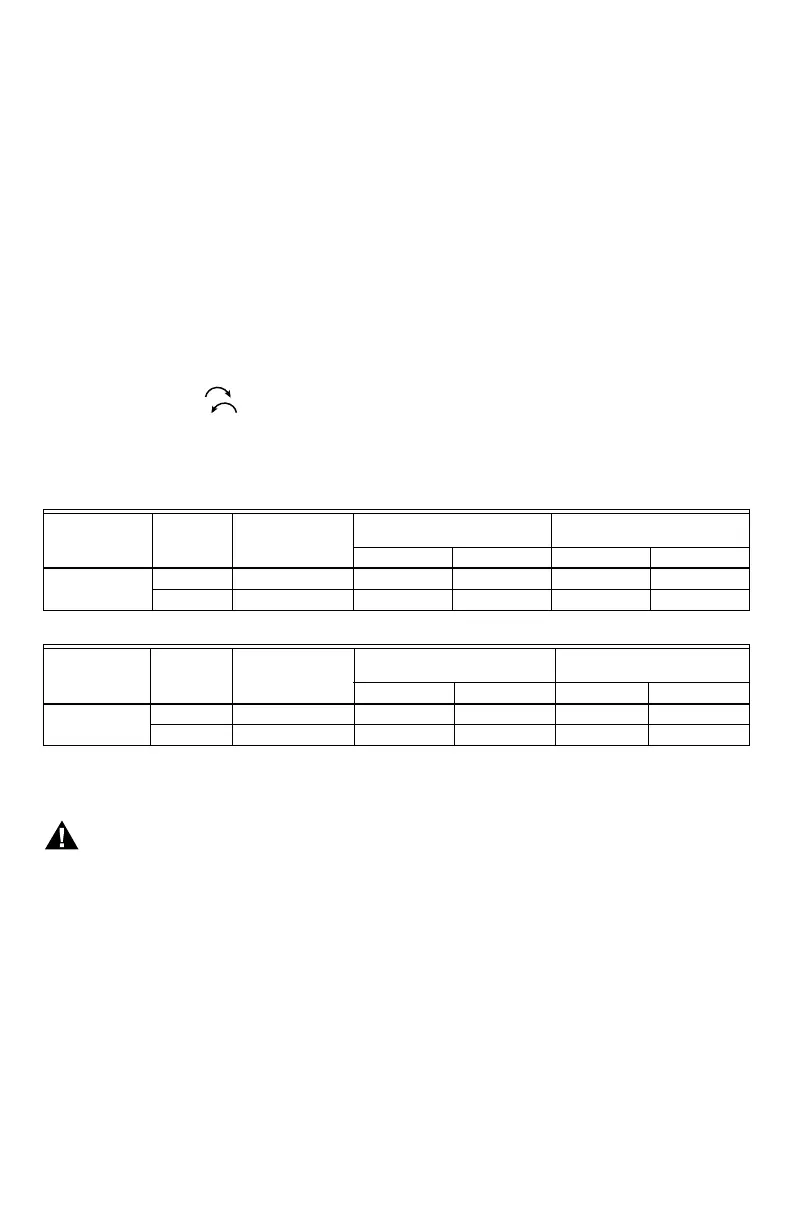
Table 7. Pressure Regulator Specification Pressures (in. wc).
Table 8. Pressure Regulator Specification Pressures (kPa).
MAINTENANCE
WARNING
Fire or Explosion Hazard.
Can cause severe injury, death or property
damage.
Do not attempt to take the control apart or clean it.
Improper cleaning or reassembly can cause gas
leakage.
Regular preventive maintenance is important in
applications such as in the commercial cooking and
agricultural and industrial industries that place a heavy
load on system controls because:
• In many such applications, particularly commercial
cooking, the equipment operates 100,000 to 200,000
cycles per year. Such heavy cycling can wear out the
gas control in one to two years.
• Exposure to water, dirt, chemicals and heat can
damage the gas control and shut down the control
system.
The maintenance program should include regular
checkout of the control as outlined in the Startup and
Checkout section, and the control system as described in
the appliance manufacturer literature.
Maintenance frequency must be determined individually
for each application. Some considerations are:
• Cycling frequency. Appliances that may cycle 200,000
times annually should be checked monthly.
• Intermittent use. Appliances that are used seasonally
should be checked before shutdown and again before
the next use.
• Consequence of unexpected shutdown. Where the
cost of an unexpected shutdown would be high, the
system should be checked more often.
• Dusty, wet, or corrosive environment. Since these
environments can cause the gas control to deteriorate
more rapidly, the system should be checked more often.
The system should be replaced if:
• It does not perform properly on checkout or
troubleshooting.
• The gas control is likely to have operated for more than
200,000 cycles.
• The control is wet or looks as if it has been wet.
Model Type
Type of
Gas
Nominal Inlet
Pressure Range
Factory Set Nominal Outlet
Pressure Setting Range
Step Full Rate Step Full Rate
Standard, Slow NAT 5.0-7.0 — 3.5 — 3.0-5.0
LP 12.0-14.0 — 10.0 — 8.0-12.0
Model Type
Type of
Gas
Nominal Inlet
Pressure Range
Factory Set Nominal Outlet
Pressure Setting Range
Step Full Rate Step Full Rate
Standard, Slow NAT 1.2-1.7 — 0.9 — 0.7-1.2
LP 2.9-3.9 — 2.5 — 2.0-3.0
 Loading...


