SV9510/SV9520 SMARTVALVE™ SYSTEM CONTROLS
3 69-2014
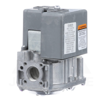
Table 5. Adapter (Flange) Part Numbers.
a
Flange kits include one flange, one O-ring and four
mounting screws.
b
Do not use flanges on control models with 3/4 in. inlet
and 3/4 in. outlet. On models with 1/2 in. inlet and 3/4 in.
outlet, use flanges only on the 1/2 in. inlet side.
PLANNING THE INSTALLATION
WARNING
Fire or Explosion Hazard.
Can cause property damage, severe injury, or
death.
Follow these warnings exactly:
1. Plan the installation as outlined below.
2. Plan for frequent maintenance as described in
the Maintenance section.
When direct ignition systems are used on central heating
equipment in barns, greenhouses, and commercial
properties and on heating appliances such as commercial
cookers, agricultural equipment, industrial heating
equipment and pool heaters, heavy demands are made
on the controls. Special steps may be required to prevent
nuisance shutdowns and control failure due to frequent
cycling, severe environmental conditions related to
moisture, corrosive chemicals, dust or excessive heat.
These applications require Honeywell Home and Building
Control Engineering review; contact your Honeywell Sales
Representative for assistance.
Review the following conditions that can apply to your
specific installation and take the precautionary steps
suggested.
Frequent Cycling
This control is designed for use on appliances that
typically cycle three to four times an hour only during the
heating season. In year-around applications with greater
cycling rates, the control can wear out more quickly.
Perform a monthly checkout.
Water or Steam Cleaning
If a control gets wet, replace it. If the appliance is likely to
be cleaned with water or steam, protect (cover) the
control and wiring from water or steam flow. Mount the
control high enough above the bottom of the cabinet so it
does not get wet during normal cleaning procedures.
High Humidity or Dripping Water
Dripping water can cause the control to fail. Never install
an appliance where water can drip on the control.
In addition, high ambient humidity can cause the control
to corrode and fail. If the appliance is in a humid
atmosphere, make sure air circulation around the control
is adequate to prevent condensation. Also, regularly
check out the system.
Corrosive Chemicals
Corrosive chemicals can attack the control, eventually
causing a failure. If chemicals are used for routine
cleaning, avoid contact with the control. Where chemicals
are suspended in air, as in some industrial or agricultural
applications, protect the control with an enclosure.
Dust or Grease Accumulation
Heavy accumulations of dust or grease can cause the
control to malfunction. Where dust or grease can be a
problem, provide covers for the control to limit
contamination.
Heat
Excessively high temperatures can damage the control.
Make sure the maximum ambient temperature at the
control does not exceed the rating of the control. If the
appliance operates at very high temperatures, use
insulation, shielding, and air circulation, as necessary, to
protect the control. Proper insulation or shielding should
be provided by the appliance manufacturer; verify proper
air circulation is maintained when the appliance is
installed.
Line Voltage Power Supply
• 120 Vac hot supply must be connected to C3, pin 2 on
SV module.
• Appliance chassis must be earth grounded.
• Earth ground and 120V supply neutral lead must be
electrically common at the breaker box.
• Control will not sense flame if these connections are
not correct.
INSTALLATION
When Installing this Product…
1. Read these instructions carefully. Failure to follow
them could damage the product or cause a
hazardous condition.
2. Check the ratings given in the instructions and on
the product to make sure the product is suitable for
your application.
3. Installer must be a trained, experienced service
technician.
4. After installation is complete, check out product
operation as provided in these instructions.
WARNING
Fire or Explosion Hazard,
Can cause property damage, severe injury or
death.
To avoid dangerous accumulation of fuel gas, turn
off gas supply at the appliance service valve
before starting installation, and perform Gas Leak
Test after completion of installation.
Inlet/Outlet
Pipe Size
Flange
Type
Part No.
a,b
Without Hex
Wrench
With Hex
Wrench
3/8 in. NPT Straight 393690-1 393690-11
Elbow 393690-2 393690-12
1/2 in. NPT Straight 393690-6 393690-16
Elbow 393690-3 393690-13
3/4 in. NPT Straight 393690-4 393690-14
Elbow 393690-5 393690-15
 Loading...


