SV9510/SV9520 SMARTVALVE™ SYSTEM CONTROLS
69-2014 4
WARNING
Electrical Shock Hazard.
Can cause severe injury, death, or property
damage.
Disconnect power supply before wiring to prevent
electrical shock or equipment damage.
IMPORTANT
Always install a sediment trap in gas supply line
to prevent contamination of ignition system
control.
CAUTION
Equipment Damage Hazard.
Improper wiring can damage equipment.
Never apply a jumper across or short the
thermostat, 24V hot or 24V common terminal in
the SV9510/SV9520 wiring harness. This can
burn out the heat anticipator in the thermostat or
damage the system transformer.
Follow the appliance manufacturer instructions if
available; otherwise, use these instructions as a guide.
Converting Ignition System Control from
Natural Gas to LP Gas Application (or LP
Gas to Natural Gas Application)
WARNING
Fire or Explosion Hazard.
Can cause property damage, severe injury or
death.
Always change the main burner orifices when
converting from natural to LP gas or from LP to
natural gas. Follow appliance manufacturer
specifications and instructions.
Ignition system controls are factory-set for natural (and
manufactured) or LP gas. Do not attempt to use an
ignition system control set for natural (manufactured) gas
on LP gas, or an ignition system control set for LP gas on
natural (manufactured) gas.
Ignition system controls with standard or slow opening
regulators (SV9510M,H/ SV9520M,H, K) can be
converted from one gas to the other with a conversion kit
(ordered separately). Order part no. 393691 to convert
from natural (manufactured) to LP gas; order part no.
394588 to convert from LP to natural (manufactured) gas.
Two-stage ignition system controls (those with N and Q
suffix letters) can be converted using a conversion kit
(ordered separately). Order part number 396021 to
convert from natural (manufactured) to LP gas; order part
number 396025 to convert from LP to natural
(manufactured) gas.
IMPORTANT
Ignition system controls with step-opening
regulators (SV9510P/SV9520P) CANNOT be
field-converted to LP or natural gas.
Install Adapters To Control
If adapters are being installed on the control, mount them
as follows:
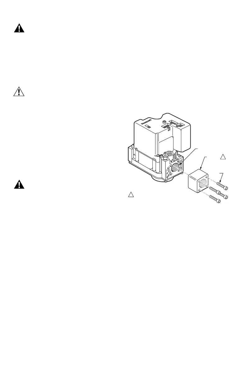
Flanges
1. Choose the appropriate flange for your application.
2. Remove the seal over the ignition system control
inlet or outlet.
3. Make sure that the O-ring is fitted in the groove of
the flange. If the O-ring is not attached or missing,
do not use the flange.
4. With the O-ring facing the ignition system control,
align the screw holes on the ignition system control
with the holes in the flange. Insert and tighten the
screws provided with the flange. See Fig.1. Tighten
the screws to 25 inch-pounds of torque to provide a
gas-tight seal.
Fig. 1. Firmly fasten flange to valve, but do not
overtighten screws.
Bushings
1. Remove the seal over the ignition system control
inlet or outlet.
2. Apply a moderate amount of good quality pipe
compound to the bushing, leaving two end threads
bare. On an LP installation, use compound resistant
to LP gas. Do not use Teflon tape.
3. Insert the bushing in the ignition system control and
carefully thread the pipe into the bushing until tight.
Complete the instructions below for installing the piping,
installing the control, and connecting the wiring. Make
sure the leak test you perform on the control after
completing the installation includes leak testing the
adapters and screws. If you use a wrench on the valve
after the flanges are installed, use the wrench only on the
flange, not on the control. See Fig. 5.
Location
The SV9510/SV9520 is mounted in the appliance
vestibule on the gas manifold.
M12168
VALVE OUTLET
FLANGE
9/64 INCH
HEX
SCREWS
(4)
1
1
DO NOT USE FLANGES ON 3/4 IN. INLET
AND 3/4 IN. OUTLET MODELS, AND ON
THE 3/4 IN. OUTLET SIDE OF 1/2 IN.
INLET AND 3/4 IN. OUTLET MODELS.
 Loading...


