SV9510/SV9520 SMARTVALVE™ SYSTEM CONTROLS
5 69-2014
CAUTION
Equipment Damage Hazard.
Improper mounting location can damage
control.
Do not mount the SmartValve™ System Control
where water can fall on the device.
IMPORTANT
These ignition system controls are shipped with
protective seals over the inlet and outlet
tappings. Do not remove the seals until ready to
connect the piping.
Install Piping to Control
All piping must comply with local codes and ordinances or
with the National Fuel Gas Code (ANSI Z223.1 NFPA No.
54), whichever applies. Tubing installation must comply
with approved standards and practices.
1. Use new, properly reamed pipe free from chips. If
tubing is used, make sure the ends are square,
deburred and clean. All tubing bends must be
smooth and without deformation.
2. Run pipe or tubing to the ignition system control. If
tubing is used, obtain a tube-to-pipe coupling to
connect the tubing to the ignition system control.
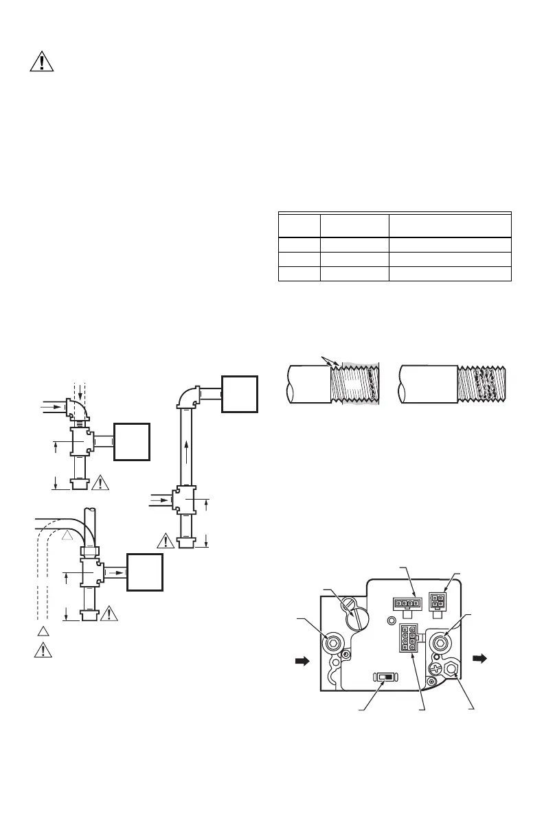
3. Install a sediment trap in the supply line to the
ignition system control. See Fig. 2.
Fig. 2. Sediment trap installation.
Install Control
1. This ignition system control can be mounted 0 to 90
degrees in any direction, including vertically, from
the upright position of the ignition system control
switch.
2. Mount the control so the gas flow is in the direction
of the arrow on the bottom of the ignition system
control.
3. Thread the pipe the amount shown in Table 6 for
insertion into ignition system control or adapters. Do
not thread pipe too far. Valve distortion or
malfunction can result if the pipe is inserted too
deeply.
Table 6. NPT Pipe Thread Length (in.)
4. Apply a moderate amount of good quality pipe
compound (do not use Teflon tape) only to the pipe,
leaving two end threads bare. On LP installations,
use a compound resistant to LP gas. See Fig. 3.
Fig. 3. Use moderate amount of pipe compound.
5. Remove the seals over the ignition system control
inlet and outlet, if necessary.
6. Connect the pipe to the ignition system control inlet
and outlet. Use a wrench on the square ends of the
ignition system control. If a flange is used, place the
wrench on the flange rather than on the ignition sys-
tem control. Refer to Fig. 4 and 5.
Fig. 4. Top view of ignition system control.
HORIZONTAL
DROP
PIPED
GAS
SUPPLY
PIPED
GAS
SUPPLY
3 IN.
(76 MM)
MINIMUM
3 IN.
(76 MM)
MINIMUM
RISER
IGNITION
SYSTEM
CONTROL
TUBING
GAS
SUPPLY
HORIZONTAL
DROP
3 IN.
(76 MM)
MINIMUM
RISER
M3343D
1
IGNITION
SYSTEM
CONTROL
IGNITION
SYSTEM
CONTROL
1
CAUTION
GAS LEAKAGE HAZARD.
FAILURE TO FOLLOW PRECAUTIONS CAN RESULT IN A GAS-FILLED
WORK AREA. SHUT OFF THE MAIN GAS SUPPLY BEFORE
REMOVING END CAP. TEST FOR GAS LEAKAGE WHEN
INSTALLATION IS COMPLETE.
ALL BENDS IN METALLIC TUBING MUST BE SMOOTH.
Pipe
Size
Thread Pipe
This Amount
Maximum Depth Pipe can
be Inserted into Control
3/8 9/16 3/8
1/2 3/4 1/2
3/4 13/16 3/4
TWO
IMPERFECT
THREADS
IGNITION
SYSTEM
CONTROL
THREAD PIPE THE AMOUNT
SHOWN IN TABLE FOR INSERTION
INTO IGNITION SYSTEM CONTROL
APPLY A MODERATE AMOUNT OF
PIPE COMPOUND ONLY TO PIPE
(LEAVE TWO END THREADS BARE).
M3344
PIPE
OFF
ON
PRESSURE REGULATOR
ADJUSTMENT (UNDER
CAP SCREW)
INLET
PRESSURE
TAP
INLET
IGNITION SYSTEM
CONTROL SWITCH
CONTROLS
CONNECTOR
PILOT
OUTLET
OUTLET
OUTLET
PRESSURE
TAP
M15045A
IGNITER
CONNECTOR
LINE VOLTAGE
CONNECTOR
C1
C2
C3
 Loading...


